
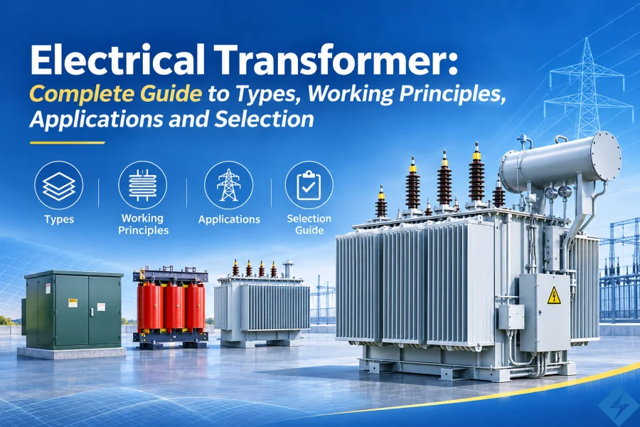
Electrical transformers are essential components of modern power systems. They make it possible to transmit electricity over long distances, distribute power to residential communities, and supply reliable electrical energy to industrial facilities, commercial buildings, renewable energy plants, and data centers.
From small distribution transformers installed on utility poles to large power transformers operating in high-voltage substations, electrical transformers serve different purposes throughout the electricity network.
However, not all transformers are designed in the same way. Their rated capacity, voltage ratio, winding configuration, insulation system, cooling method, and installation structure depend on the specific electrical application.
This guide explains what an electrical transformer is, how it works, its main types, internal components, technical specifications, applications, and the factors engineers and buyers should consider when selecting a transformer.
1. What Is an Electrical Transformer?
An electrical transformer is a static electrical device that transfers alternating-current (AC) electrical energy between two or more circuits through electromagnetic induction.
Its primary function is to increase or decrease voltage while maintaining the same supply frequency under normal operation.
Transformers are widely used in electrical generation, transmission, distribution, and industrial power systems.
Ad esempio:
Power plants use step-up transformers to increase generator voltage for long-distance transmission.
Electrical substations use power transformers to transfer electricity between different voltage levels.
Distribution transformers reduce medium-voltage electricity to levels suitable for commercial and residential consumption.
Industrial transformers provide the voltage required by machinery, production lines, and specialized electrical equipment.
Renewable energy projects use transformers to connect solar and wind generation systems to electrical networks.
Without electrical transformers, modern power transmission and distribution systems would be considerably less efficient and more difficult to operate.
Why Are Electrical Transformers Important?
Electricity transmitted over long distances requires high voltage to reduce current and minimize resistive power losses.
The relationship between electrical power, voltage, and current can be expressed as:
P = V × I
For a given power level, increasing voltage reduces the current required for transmission.
Since conductor losses are proportional to the square of current, reducing current significantly decreases transmission losses.
At the receiving end, transformers reduce voltage to suitable levels for local distribution and electrical equipment.
This makes transformers essential for efficient, reliable, and economical electricity supply.
2. How Does an Electrical Transformer Work?
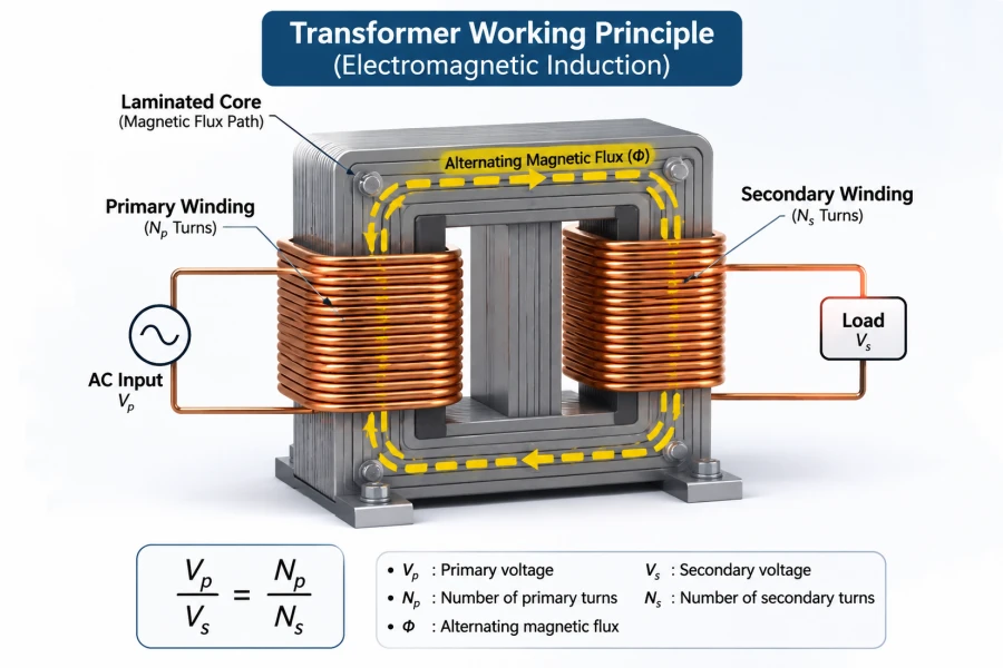
An electrical transformer operates based on the principle of electromagnetic induction.
When alternating current flows through the primary winding, it produces a changing magnetic field. This magnetic field travels through the transformer core and links with the secondary winding, inducing an electromotive force (voltage).
If the secondary winding is connected to a load, current flows through the secondary circuit, transferring electrical energy from the primary side.
The primary and secondary windings are magnetically coupled but are not normally electrically connected.
Main Working Process
The operation of a transformer can be explained in five steps:
Power Input: AC voltage is supplied to the primary winding.
Magnetic Field Generation: Current flowing through the primary winding creates alternating magnetic flux.
Magnetic Flux Transfer: The transformer core provides a low-reluctance path for the magnetic flux.
Voltage Induction: The changing magnetic flux induces voltage in the secondary winding.
Power Output: The secondary winding supplies electrical energy to the connected load at the designed voltage level.
Transformer Voltage Ratio Formula
The ideal transformer voltage ratio is determined by the number of turns in the primary and secondary windings.
Vp / Vs = Np / Ns
Dove:
Vp = Primary voltage
Vs = Secondary voltage
Np = Number of primary winding turns
Ns = Number of secondary winding turns
For example, consider a transformer with a primary voltage of 11 kV and a secondary voltage of 0.4 kV.
The transformer reduces the voltage from 11,000 V to 400 V for low-voltage distribution.
Step-Up vs. Step-Down Transformers
A step-up transformer has more turns in its secondary winding than in its primary winding. It increases the output voltage.
A step-down transformer has fewer turns in its secondary winding. It reduces the output voltage.
Both types operate according to the same electromagnetic induction principle.
3. Main Components of an Electrical Transformer
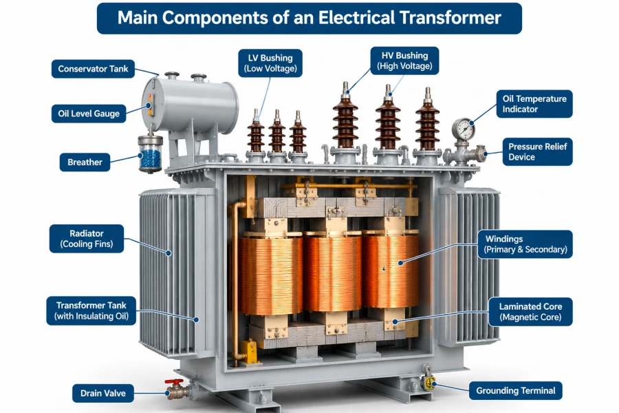
The construction of a transformer directly affects its electrical performance, efficiency, insulation reliability, cooling capacity, and service life.
Although transformer designs vary according to their ratings and applications, most conventional power and distribution transformers contain the following components.
3.1 Magnetic Core
The transformer core provides a path for magnetic flux between the primary and secondary windings.
It is commonly manufactured from laminated cold-rolled grain-oriented silicon steel (CRGO).
The core laminations help reduce eddy current losses, while the magnetic properties of the steel influence hysteresis losses.
Some specialized transformer designs use amorphous metal cores to reduce no-load losses.
3.2 Primary and Secondary Windings
Windings are insulated electrical conductors arranged around the transformer core.
The primary winding receives electrical energy, while the secondary winding delivers energy to the connected circuit.
Common winding materials include:
Copper: Offers high electrical conductivity and excellent mechanical properties.
Aluminum: Provides a lighter and often more economical alternative.
The selection depends on rated current, transformer capacity, temperature rise, design requirements, and project budget.
3.3 Insulation System
The insulation system separates energized components from each other and from grounded structures.
Depending on the transformer type, insulation materials may include:
Electrical insulation paper
Pressboard
Mineral insulating oil
Natural ester insulating fluid
Epoxy resin
Insulating films and composite materials
Insulation performance is critical to transformer reliability and electrical safety.
3.4 Transformer Tank and Enclosure
Oil-immersed transformers normally use a steel tank to contain the core, windings, and insulating liquid.
The tank protects internal components against environmental conditions and provides mechanical support.
Dry-type transformers generally use an open structure or protective metal enclosure, depending on the installation environment.
3.5 Cooling System
Transformer losses generate heat during operation.
The cooling system transfers this heat away from the core and windings to maintain acceptable operating temperatures.
Common arrangements include ONAN, ONAF, and natural or forced air cooling for dry-type transformers.
3.6 Bushings and Terminals
Bushings provide insulated connections between internal windings and external electrical circuits.
Their voltage ratings, current ratings, insulation levels, and physical arrangements must match the transformer design.
3.7 Tap Changer
A tap changer adjusts the effective turns ratio of a transformer to compensate for changes in system voltage.
Two common types are:
Off-Circuit Tap Changer (OCTC): Requires the transformer to be de-energized before changing the tap position.
On-Load Tap Changer (OLTC): Allows voltage adjustment while the transformer remains energized and carries its designed load.
4. Main Types of Electrical Transformers
Electrical transformers can be classified according to their function, voltage level, winding configuration, insulation system, cooling method, and installation structure.
Understanding these classifications helps engineers and procurement professionals select suitable equipment for different applications.
4.1 Power Transformers
Trasformatori di potenza are primarily used in high-voltage transmission networks and large electrical substations.
They transfer electrical energy between high-voltage network sections and are commonly installed at power generation facilities and grid substations.
Typical characteristics include:
High voltage ratings, including 110 kV, 220 kV, and 500 kV.
Large capacities ranging from several MVA to hundreds of MVA.
Advanced cooling and insulation systems.
Optional on-load tap changers.
Specialized protection and monitoring accessories.
4.2 Distribution Transformers
Trasformatori di distribuzione reduce medium-voltage electricity to lower voltage levels for final consumption.
They are commonly used in utility distribution networks, commercial buildings, factories, and residential communities.
Typical distribution transformer ratings include:
25 kVA, 50 kVA, 100 kVA, 250 kVA, 500 kVA, 1,000 kVA, 2,000 kVA, and higher customized ratings.
Common voltage configurations include:
11 kV / 0.4 kV
13.2 kV / 0.48 kV
22 kV / 0.4 kV
33 kV / 0.415 kV
Actual ratings and configurations depend on local grid standards and project requirements.
4.3 Single-Phase Transformers
Single-phase transformers operate in single-phase AC electrical systems.
They are commonly used for residential distribution, rural electrification, lighting systems, and smaller commercial loads.
Tra le applicazioni tipiche figurano:
Residential distribution networks
Piccoli edifici commerciali
Specialized electrical equipment
4.4 Three-Phase Transformers
Three-phase transformers are designed for three-phase electrical power systems.
They are widely used in industrial plants, commercial buildings, utility substations, renewable energy installations, and large distribution networks.
Compared with single-phase units, three-phase transformers provide an integrated solution for supplying balanced three-phase loads.
Common connection groups include Dyn11, Yyn0, YNd11, and other project-specific configurations.
4.5 Oil-Immersed Transformers
Oil-immersed transformers use insulating liquid for both electrical insulation and heat transfer.
The liquid circulates through the transformer to help remove heat generated by the core and windings.
Common insulating liquids include mineral oil and natural ester fluids.
Advantages include:
Effective cooling performance
Suitability for outdoor installations
Wide capacity range
Flexible configurations for distribution and power applications
They are widely used in utility networks, industrial facilities, substations, and renewable energy projects.
4.6 Dry-Type Transformers
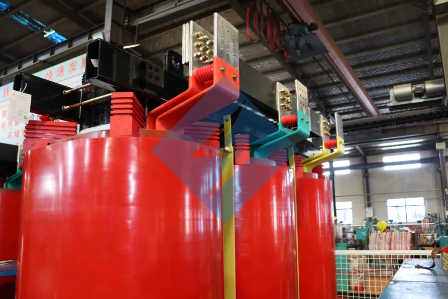
Trasformatori a secco use air and solid insulation systems instead of liquid insulation.
Cast resin transformers are a common dry-type design.
They are frequently installed in indoor electrical rooms, commercial buildings, hospitals, factories, tunnels, and data centers.
Key characteristics include:
No liquid insulating oil
Suitable for many indoor applications
Reduced risk of insulating liquid leakage
Available in natural and forced air cooling configurations
4.7 Pad-Mounted Transformers
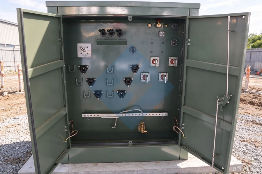
Trasformatori su basamento are ground-mounted distribution transformers installed inside locked, weather-resistant metal enclosures on concrete pads.
They are widely used in underground distribution networks, residential developments, commercial facilities, industrial parks, and renewable energy projects.
Tra le configurazioni più comuni figurano:
Trasformatori monofase montati su piastra
Three-phase pad-mounted transformers
Radial-feed designs
Loop-feed designs
Dead-front and live-front configurations
Depending on the project, pad-mounted transformers can incorporate integrated high-voltage and low-voltage compartments, fuses, switching devices, and other protective accessories.
4.8 Pole-Mounted Transformers
Pole-mounted transformers are installed on utility poles and are commonly used in overhead electrical distribution networks.
They are available in single-phase and three-phase configurations, depending on the network design.
Tra le applicazioni tipiche figurano:
Elettrificazione rurale
Distribuzione elettrica residenziale
Overhead utility networks
Agricultural power supply
Small commercial installations
5. Transformer Cooling Methods
Cooling is an important part of transformer design because electrical losses generate heat in the core and windings.
The cooling arrangement must be selected according to transformer capacity, operating conditions, ambient temperature, and installation requirements.
Common Oil-Immersed Cooling Methods
Dry-Type Cooling Methods
The correct cooling arrangement should be determined during engineering design rather than selected only according to the transformer’s rated capacity.
6. Electrical Transformer Ratings and Technical Specifications
Selecting an electrical transformer requires more than identifying its rated capacity.
Engineers must evaluate electrical, mechanical, thermal, insulation, and environmental requirements.
The following parameters are commonly included in transformer datasheets and technical specifications.
Common Transformer Voltage Levels
Transformer voltage configurations vary significantly between countries and electrical networks.
Tra gli esempi figurano:
These are representative configurations, not universal standards. Actual voltage arrangements must be verified against the local utility and project specifications.
7. Transformer Efficiency and Electrical Losses
Transformer efficiency measures how effectively electrical energy is transferred from the input side to the output side.
The basic efficiency formula is:
Efficiency (%) = (Output Power / Input Power) × 100
The main transformer losses are divided into two categories.
7.1 No-Load Losses
No-load losses mainly occur in the transformer core and are present whenever the transformer is energized.
They are primarily associated with magnetic hysteresis and eddy currents.
Core material, magnetic flux density, and core manufacturing quality influence these losses.
7.2 Load Losses
Load losses primarily result from electrical resistance in the windings.
They increase with current and are commonly evaluated at a specified reference temperature.
Winding material, conductor dimensions, winding design, and operating temperature influence load losses.
How to Improve Transformer Efficiency
Several design and manufacturing factors can improve transformer efficiency:
Selecting suitable low-loss core materials.
Optimizing magnetic flux density.
Using appropriately sized copper or aluminum conductors.
Improving winding design and manufacturing accuracy.
Minimizing unnecessary electrical and structural losses.
Selecting a suitable transformer rating for the actual load profile.
A transformer should be evaluated using both its purchase price and its expected lifetime operating losses.
8. Applications of Electrical Transformers
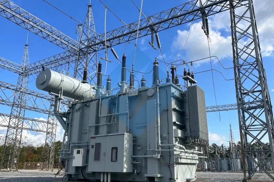
Electrical transformers are used throughout modern electrical infrastructure.
8.1 Utility and Electrical Substations
Utilities use power and distribution transformers to transfer electricity between transmission and distribution voltage levels.
They support grid expansion, voltage conversion, and reliable electricity delivery.
8.2 Industrial Manufacturing
Factories require transformers to supply motors, production machinery, process equipment, furnaces, and auxiliary electrical systems.
Transformer ratings and configurations must match the facility’s connected load and operating conditions.
8.3 Solar Power Plants
Solar photovoltaic systems generate electricity through DC-to-AC conversion equipment.
Step-up transformers increase the inverter output voltage to the medium-voltage level required for collection systems and grid interconnection.
Common configurations include 0.4 kV, 0.415 kV, or 0.69 kV on the low-voltage side, with medium-voltage outputs such as 11 kV, 22 kV, or 33 kV, depending on project design.
8.4 Wind Power Generation
Wind turbines use specialized transformers to connect generator and converter systems to wind farm collection networks.
These transformers must accommodate project-specific voltage levels, operating conditions, and environmental requirements.
8.5 Battery Energy Storage Systems (BESS)
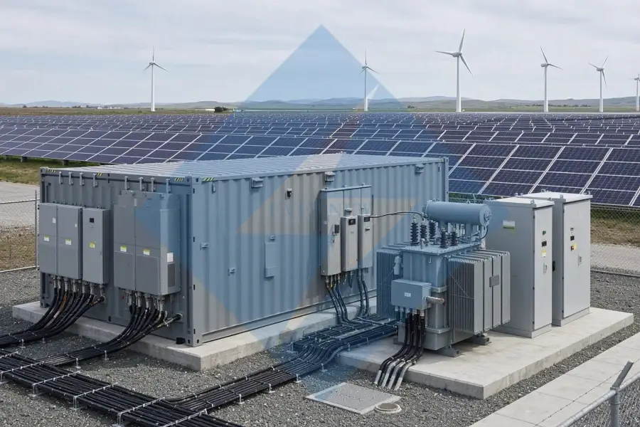
Battery energy storage systems require transformers to connect power conversion systems (PCS) with medium-voltage electrical networks.
Depending on the system architecture, transformers may be used between the PCS output and the site’s collection or grid connection system.
Important considerations include:
Bidirectional power flow
Rated capacity and overload requirements
Prestazioni armoniche
Rapporto di tensione
Impedenza
Cooling arrangement
Operating duty and environmental conditions
8.6 Data Centers
Data centers depend on reliable electrical infrastructure to supply servers, cooling equipment, UPS systems, and other critical loads.
Dry-type transformers and oil-immersed power transformers may both be used, depending on their location and electrical system architecture.
Selection should consider load growth, redundancy, harmonic conditions, efficiency, and installation space.
8.7 Commercial and Residential Buildings
Commercial buildings, shopping centers, hospitals, residential communities, and office complexes use distribution transformers to supply lighting, HVAC systems, elevators, and general electrical equipment.
9. How to Select the Right Electrical Transformer
Selecting the correct transformer is essential for electrical safety, reliable operation, and long-term operating efficiency.
Before requesting a quotation, buyers and engineers should prepare the following information.
Step 1: Determine the Required Capacity
Calculate the connected load and expected demand.
Transformer capacity is generally expressed in kVA or MVA.
The selected rating should account for load characteristics, starting currents, future expansion, and applicable design requirements.
Step 2: Confirm Primary and Secondary Voltages
Identify the actual system voltage on both sides of the transformer.
Ad esempio:
11 kV / 400 V
13.8 kV / 480Y/277 V
22 kV / 400 V
33 kV / 690 V
The voltage configuration must match the electrical network and connected equipment.
Step 3: Select Single-Phase or Three-Phase
Choose the phase configuration according to the electrical supply system and load requirements.
Step 4: Choose the Transformer Type
Consider the installation environment and application.
Ad esempio:
Oil-immersed transformer for many outdoor utility and industrial applications.
Dry-type transformer for indoor installations.
Pad-mounted transformer for underground distribution networks.
Pole-mounted transformer for overhead distribution systems.
Power transformer for high-voltage substations and transmission networks.
Step 5: Confirm Winding Material and Core Design
Select copper or aluminum windings according to electrical performance, weight, cost, and project specifications.
Core material should be evaluated according to the required loss performance and design.
Step 6: Confirm Applicable Standards
Different markets use different technical standards.
Common standards include:
IEC 60076: Power transformers.
IEEE C57 series: Power and distribution transformer standards.
CSA C88: Power transformers and reactors.
DOE efficiency requirements: Applicable US energy conservation requirements.
The specific standard and edition should be confirmed for the destination market and product category.
Step 7: Review Protection and Accessories
Depending on the transformer type, requirements may include:
Surge arresters
Fuses and circuit protection
Pressure relief devices
Temperature indicators
Liquid level indicators
Commutatori
Monitoring and alarm systems
Step 8: Evaluate Manufacturer Capability
A reliable transformer manufacturer should have suitable engineering resources, production facilities, quality control procedures, and testing capabilities.
Buyers should review:
Factory manufacturing experience.
Engineering and design capabilities.
Winding and core manufacturing facilities.
Testing equipment and procedures.
Relevant certifications and product compliance.
Previous project references.
Warranty and after-sales support.
10. Transformer Manufacturing and Quality Testing
Transformer reliability depends on both engineering design and manufacturing quality.
A professional manufacturing process typically includes core cutting, winding production, insulation assembly, active-part assembly, tank fabrication, final assembly, and electrical testing.
Core Manufacturing
Silicon steel sheets are cut and assembled according to the magnetic core design.
Accurate cutting and assembly help control core losses and noise.
Winding Manufacturing
Copper or aluminum conductors are processed into primary and secondary windings.
Winding dimensions, insulation arrangements, mechanical strength, and manufacturing accuracy are important quality considerations.
Active Part Assembly
The core and windings are assembled with insulation structures and other internal components.
The active part is prepared for tank installation and subsequent manufacturing processes.
Final Assembly
The transformer tank, bushings, cooling components, accessories, and external connections are installed according to the approved design.
Routine and Additional Testing
Typical routine tests include:
Winding resistance measurement.
Voltage ratio measurement.
Polarity and vector group verification.
No-load loss and current measurement.
Load loss and impedance measurement.
Applied voltage test.
Induced voltage test.
Insulation-related tests as specified.
Additional type and special tests may be required depending on the applicable standard and project specification.
A factory test report provides important evidence of the transformer’s measured performance and compliance with the agreed technical requirements.
11. Transformer Standards and International Market Requirements
Electrical transformer requirements vary by country, application, voltage level, and customer specifications.
Commonly referenced international standards include:
For North American projects, buyers may also require specific ANSI/IEEE configurations, applicable UL-recognized insulation systems, CSA certification, or other project-specific approvals.
For European projects, IEC requirements and applicable energy-efficiency regulations should be reviewed.
A manufacturer’s general certification portfolio does not automatically mean that every transformer model is certified for every market. Compliance should be confirmed for the specific product and project.
12. Why Choose Evernew Transformer?
Evernew Transformer supplies electrical transformers for utility, commercial, industrial, and renewable energy applications.
With engineering support and manufacturing capabilities across distribution and power transformer product ranges, Evernew provides customized solutions for different electrical systems and international markets.
Transformer Product Range
Evernew’s main product categories include:
Trasformatori di potenza
Trasformatori di distribuzione
Trasformatori in olio
Trasformatori a secco
Trasformatori montati su piastra
Trasformatori montati su palo
Three-Phase Transformers
Single-Phase Transformers
Specialized Industrial Transformers
Customized Electrical Transformer Solutions
Transformer designs can be evaluated according to project-specific requirements, including:
Rated capacity and voltage ratio.
Single-phase or three-phase configuration.
Copper or aluminum windings.
CRGO or amorphous core materials.
Oil-immersed or dry-type insulation systems.
ONAN, ONAF, AN, or AF cooling arrangements.
Vector group and impedance.
Indoor or outdoor installation.
Applicable international standards.
From distribution transformer projects to large power transformer applications, the engineering team can review technical requirements and recommend suitable designs.
Looking for an Electrical Transformer Manufacturer?
Contact Evernew Transformer to discuss your project requirements, request technical specifications, and obtain a customized quotation.
Provide your required capacity, primary voltage, secondary voltage, frequency, transformer type, and installation environment to help our engineering team evaluate your application.
13. Frequently Asked Questions About Electrical Transformers
1. What is the main purpose of an electrical transformer?
The main purpose of an electrical transformer is to increase or decrease AC voltage through electromagnetic induction. Transformers enable efficient electricity transmission and distribution while supplying suitable voltage levels to electrical equipment.
2. What are the main types of electrical transformers?
Common types include power transformers, distribution transformers, single-phase transformers, three-phase transformers, oil-immersed transformers, dry-type transformers, pad-mounted transformers, and pole-mounted transformers.
3. What is the difference between a power transformer and a distribution transformer?
Power transformers are primarily used in transmission networks and high-voltage substations, while distribution transformers reduce voltage to levels suitable for local electricity distribution and end users.
4. What is the difference between an oil-immersed and a dry-type transformer?
Oil-immersed transformers use insulating liquid for insulation and cooling. Dry-type transformers use air and solid insulation materials, making them suitable for many indoor applications.
5. What is the difference between a step-up and a step-down transformer?
A step-up transformer increases voltage from primary to secondary, while a step-down transformer decreases voltage.
6. What capacity electrical transformer do I need?
The required capacity depends on the total electrical demand, load characteristics, power factor, starting current, future expansion, and project design requirements. A qualified engineer should evaluate these factors before selecting a transformer rating.
7. Are electrical transformers available in 50 Hz and 60 Hz?
Yes. Transformers can be designed for 50 Hz or 60 Hz operation. The frequency must be specified during the design stage because it affects magnetic flux density, core design, and other electrical characteristics.
8. How long does an electrical transformer last?
Transformer service life depends on design quality, insulation condition, operating temperature, loading, maintenance, and environmental conditions. Properly designed and maintained transformers can operate for several decades.
9. What standards apply to electrical transformers?
Common standards include IEC 60076, the IEEE C57 series, and applicable CSA standards. The required standard depends on the destination market and transformer application.
10. How can I obtain a quotation for an electrical transformer?
To request a quotation, provide the rated capacity, primary and secondary voltages, frequency, phase configuration, winding material, cooling method, applicable standards, quantity, and destination country.
Evernew Transformer can review your requirements and provide a customized technical proposal and commercial quotation.
Need a Transformer for Your Next Project?
Whether you require a distribution transformer, power transformer, pad-mounted transformer, pole-mounted transformer, or dry-type transformer, Evernew can evaluate your requirements and provide a solution based on your project specifications.
Contact Evernew Transformer for Technical Support and Factory Pricing.
