Introduction
Transformer impedance, often expressed as Z%, is one of the most critical parameters in power system design. It not only influences short-circuit current, voltage regulation, and load sharing but also affects the safety, reliability, and cost-efficiency of industrial and utility projects.
For engineers, EPC contractors, and utility decision-makers, understanding how transformer impedance works, how it’s calculated, and how to select the right value is essential for designing optimized power systems.
This guide explains transformer impedance in detail, its impact on power systems, and practical tips for selecting transformers with the appropriate Z% for your project.
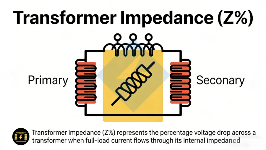
What is Transformer Impedance (Z%)?
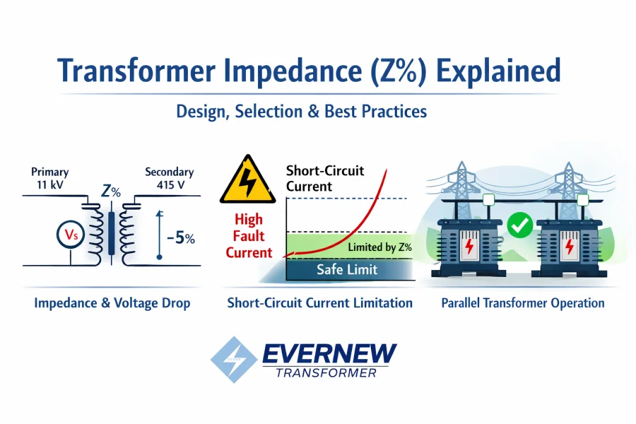
Transformator impedance (Z%) represents the percentage voltage drop across a transformer when full-load current flows through its internal impedance.
Key points:
Components: Resistance (R) + Leakage Reactance (X)
Effect: Limits short-circuit current and influences voltage regulation under load
Representation: Usually given in percentage of rated voltage
Contoh:
A 1000 kVA, 11 kV / 415 V transformer dengan 5% Z means:
5% of rated voltage is required to circulate rated current through the transformer’s impedance
Limits short-circuit current to 20 times rated current
Proper understanding of Z% ensures safety, correct sizing of protective devices, and efficient system operation.
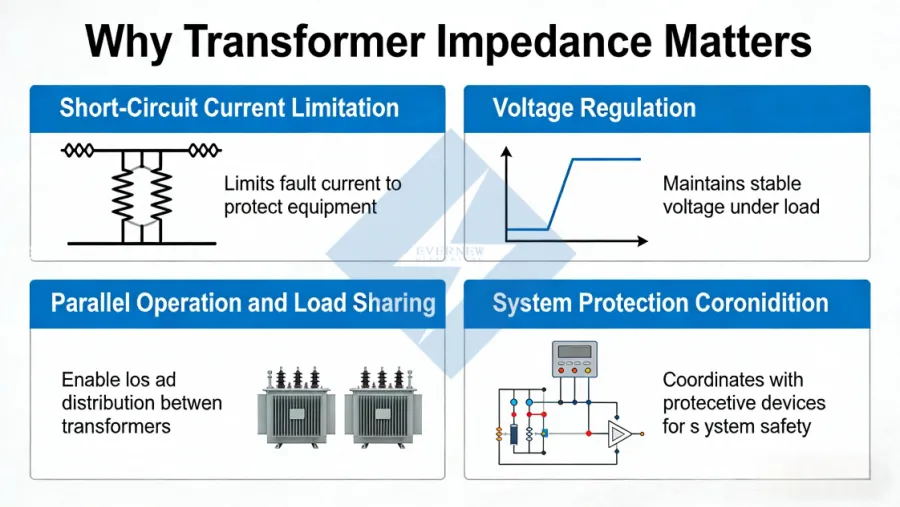
Why Transformer Impedance Matters
1. Short-Circuit Current Limitation
High fault currents can damage transformers, switchgear, and downstream equipment.
Correct Z% prevents excessive currents and ensures protective devices function correctly.
2. Voltage Regulation
Transformer impedance directly affects secondary voltage stability under varying loads.
Lower Z% → better voltage regulation, but higher short-circuit currents
Higher Z% → lower fault currents, but higher voltage drop under load
3. Parallel Operation and Load Sharing
In multiple-transformer installations, matched impedances are crucial for proportional load sharing.
Misaligned Z% can cause circulating currents, overloading one unit, and underloading another.
4. System Protection Coordination
Transformer impedance influences relay settings, breaker selection, and fault response time.
How Transformer Impedance is Calculated
Z% Formula: Z%=(Voltage Drop at FullLoad/Rated Voltage)×100%
Typical Impedance Ranges by Transformer Capacity:
| Transformer Rating | Typical Z% | Aplikasi |
|---|---|---|
| 500 kVA – 1 MVA | 4–6% | Industrial & commercial distribution |
| 2 – 5 MVA | 5–7% | Medium-voltage industrial plants |
| 10 MVA+ | 6–10% | Utility transmission & substations |
Tip: Always check whether the transformer specification follows IEC 60076 (Europe & global) atau IEEE C57.12 (USA) standards for impedance.
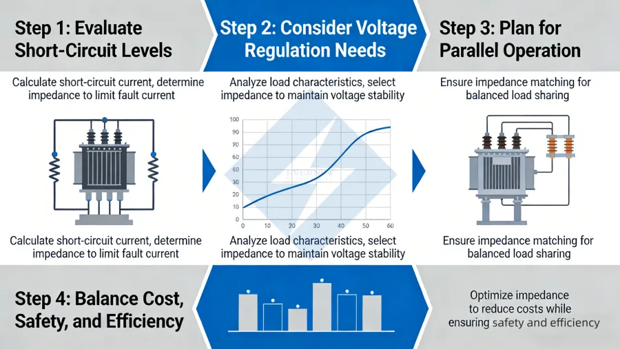
Designing and Selecting Transformer Impedance
Step 1: Evaluate Short-Circuit Levels
Measure maximum fault current at the installation site
Select Z% to ensure fault currents stay within switchgear and breaker capacity
Step 2: Consider Voltage Regulation Needs
Lower Z% → better voltage regulation for sensitive industrial loads
Higher Z% → safer short-circuit current but increased voltage drop under full load
Step 3: Plan for Parallel Operation
Impedance must match all transformers operating in parallel
Prevents circulating currents and uneven load distribution
Step 4: Balance Cost, Safety, and Efficiency
Low Z% may increase protection costs due to higher fault currents
High Z% may slightly reduce system efficiency but enhance safety
Aim for an optimized balance depending on project priorities
Common Misconceptions
“Lower impedance is always better”
Lower Z% increases short-circuit current → requires stronger protection and can increase system risk.
Ignoring parallel operation effects
Mismatched impedance can lead to unbalanced load sharing and transformer overheating.
Overlooking international standards
IEC vs IEEE differences can affect short-circuit calculations and Z% selection.
Transformer Impedance vs Project Cost and Efficiency
Proper impedance selection affects:
Short-circuit protection device sizing
Voltage regulation performance
Overall system reliability and operational cost
Contoh:
A 5% Z transformer may provide optimal balance for 1000 kVA–2000 kVA industrial transformers, offering sufficient short-circuit limitation while maintaining good voltage regulation.
Practical Tips for Engineers
Always request the transformer’s impedance in the specification sheet before project approval.
Verify Z% values for both high-voltage and low-voltage windings.
Coordinate with switchgear and protective device ratings to avoid oversizing or undersizing.
For parallel operation, ensure all transformers in the system have compatible Z%.
Kesimpulan
Transformer impedance (Z%) is not just a technical specification – it is a key factor that influences:
Safety during faults
Voltage stability under load
Parallel transformer operation
Overall system cost and efficiency
For industrial, utility, and renewable energy projects, choosing the right transformer impedance ensures optimal performance and long-term reliability.
At Evernew Transformer, we provide custom-designed transformers with precise impedance control, 100% copper windings, and full IEC/IEEE compliance, tailored for:
Industrial plants
Distribution substations
Integrasi energi terbarukan
Parallel transformer installations
📩 Contact Evernew today to discuss your project requirements and get a tailored transformer solution with optimized Z% for your system.