Expert Guide by the EverNew Transformer Engineering Team
Selecting a distribution transformer is not a mere procurement transaction; it is a high-stakes, long-term engineering decision that directly dictates system reliability, operational safety, energy efficiency, and total lifecycle costs for the next 30 to 40 years. An optimized choice prevents catastrophic blackouts and minimizes core/copper losses, while an incorrect specification can lead to premature insulation breakdown, localized grid instability, and massive financial penalties.
This comprehensive guide is compiled by the senior engineering and design team at Transformador EverNew. The technical insights, selection logics, and empirical data presented below are drawn directly from our real-world project execution across global utility networks, heavy industrial complexes, and major EPC infrastructure projects in Asia, the Middle East, Africa, Europe, and South America.
1. Understanding Distribution Transformers in Real Power Systems
A distribution transformer serves as the final, critical stage of voltage transformation in an electrical power distribution network. Its primary physics-based function is to step down medium-voltage (MV) electrical power—typically ranging from 11 kV a 34.5 kV—to utilization-level low voltage (LV), safely usable by residential, commercial, and industrial loads (typically 208 V to 600 V).
[Transmission Grid: High Voltage]
       │
       ▼
[Substation: Step-Down to Medium Voltage (11kV - 34.5kV)]
       │
       ▼
[Distribution Transformer: Step-Down to Low Voltage (208V - 600V)] ◄── (EverNew Engineering Focus)
       │
       ├─► Urban Underground Systems (Pad-Mounted)
       ├─► Renewable Energy Substations (Solar/Wind)
       ├─► Industrial Manufacturing Plants (Oil-Immersed/Dry-Type)
       └─► Commercial Infrastructure & Data Centers
In modern, decentralized power grids, the operational profile of these assets has evolved. They are no longer passive step-down units; they must handle bidirectional power flows, harmonic distortions from non-linear loads, and rapid thermal cycling.
Real-World Application Profiles
-
Urban Underground Distribution Systems: Characterized by high load density, limited physical footprint, and stringent public safety mandates. These systems require high-reliability configurations capable of sub-surface or surface-level public installation.
-
Industrial Manufacturing Plants: Demanding heavy inductive loads, continuous high-duty cycles, and resistance to severe environmental contaminants, voltage dips, and short-term overloads.
-
Renewable Energy Substations (Solar/Wind): Exposed to highly cyclical load profiles, extreme solar-induced thermal variations, harmonic frequencies generated by inverters, and potential DC bias in the windings.
-
Commercial Building & Data Center Power Systems: Requiring maximum fire-suppression compliance, low acoustic noise signatures, high harmonic tolerance (K-factor ratings), and seamless integration with localized Uninterruptible Power Supply (UPS) topologies.
-
Utility Grid Distribution Nodes: Demanding massive deployment scalability, minimal no-load losses for regulatory environmental compliance, and high short-circuit withstand capabilities.
🛠️ EverNew Internal Link Portfolio:
To explore our specific product line technical parameters, view our core product pages:
2. Critical Technical Parameters: The Engineering Selection Matrix
When specifying a distribution transformer, procurement teams often over-rely on basic kVA and voltage ratings. True engineering selection requires a deep dive into electromagnetic, thermal, and mechanical parameter configurations.
2.1 Rated Capacity (kVA Selection Logic)
Sizing a transformer incorrectly is one of the costliest engineering errors. Under-sizing triggers thermal runaway and accelerates insulation degradation according to Arrhenius’ thermal aging laws. Over-sizing incurs unnecessary upfront capital expenditure and inflicts ongoing financial penalties via continuous, unmitigated no-load (core) losses over decades.
The engineering calculation for total required capacity (S_req in kVA) must account for the continuous base load, power factor (cos phi), coincident factors, localized harmonic profiles (K-factor), and explicit allowances for future infrastructure expansion.
[ S_req Calculation Formula ]

                 P_base * K_expansion
    S_req = ────────────────────────────── + S_motor_start
              cos_phi * eta_coincidence
Dónde:
-
P_base = Calculated peak active power demand (kW)
-
K_expansion = Future growth margin factor (typically 1.20 to 1.30, representing a 20% to 30% reserve)
-
cos_phi = System power factor
-
eta_coincidence = Diversity factor of simultaneous loads
-
S_motor_start = Transient apparent power spike during large motor start-ups
Standard Application Ranges
-
50 kVA – 250 kVA: Single-phase or small three-phase pole-mounted configurations serving residential clusters, agricultural irrigation networks, or light commercial outposts.
-
315 kVA – 1250 kVA: Standard commercial structures, shopping complexes, high-density residential high-rises, and light-duty industrial manufacturing workshops.
-
1600 kVA – 5000 kVA: Heavy industrial processing plants (chemical, automotive, steel), large-scale data center campus modules, utility substations, and utility-scale solar/wind farms.
2.2 Voltage Systems and Regional Grid Standards Mapping
Mismatched voltage ratings or incorrect tapping configurations will prevent grid synchronization or cause severe equipment failure. Transformers must be engineered to match the exact primary distribution and secondary utilization voltages of the target region, incorporating manual or automatic tap changers (De-energized Tap Changer – DETC, or On-Load Tap Changer – OLTC) to counteract localized grid fluctuations.
| Nominal Primary Voltage | Common Secondary Voltage | Standard Frequency | Target Regions / Deployment Spheres |
| 11 kV / 22 kV | 400V / 230V (Three-Phase) | 50 Hz | United Kingdom, European Union, Southeast Asia, India, Middle East, Africa (IEC Standard Grid) |
| 13.2 kV / 13.8 kV / 24.94 kV / 34.5 kV | 480Y/277V, 208Y/120V, 240V Delta | 60 Hz | United States, Canada, Mexico, parts of South America (ANSI/IEEE Systems) |
| 22 kV / 33 kV | 415V / 690V | 50 Hz / 60 Hz | Heavy Industrial Applications, Long-distance Rural Lines, Wind Farm Collector Networks |
2.3 Frequency Impact: 50 Hz vs. 60 Hz Core Physics
Operating a transformer outside its native design frequency compromises its core design. A 60 Hz transformer energized on a 50 Hz grid experiences a 20% reduction in inductive reactance. This causes a proportional increase in excitation current, driving the magnetic core into saturation, escalating core losses, and inducing extreme localized overheating.
Conversely, operating a 50 Hz transformer on a 60 Hz system is generally permissible from a saturation standpoint, but requires precise recalculations of short-circuit impedance and voltage regulation drops due to increased eddy current losses. Core flux density (B_max) must be precisely calculated during the design phase:
Core Flux Density Proportionality:
B_max ∝ V / (f * A * N)
Where V is voltage, f is frequency, A is core cross-sectional area, and N is the number of turns. EverNew engineers modify core cross-sections and silicon steel grades depending on the operational frequency to ensure peak efficiency.
2.4 Vector Group Configuration (Phase and Zero-Sequence Dynamics)
The vector group configuration defines the phase displacement and geometric connection strategy of the primary and secondary windings. This choice directly impacts the unit’s ability to handle unbalanced loads, clear third-harmonic currents (3rd, 9th, 15th order harmonics), and integrate with existing grounding schemes.
      Primary (Delta - D)                  Secondary (Wye - y) with Neutral (n)

              /                                        │
             /                                         ├───► Phase A
            /____                                      │
         Phase A, B, C                                  ├───► Phase B
     (Circulates 3rd Harmonics)                         │
                                                        ├───► Phase C
                                                        │
                                                       ┴─ Node (n) -> Grounded Neutral
-
Dyn11 (Delta Primary, Star/Wye Secondary with Neutral, 30° Lead): The gold standard configuration for global distribution systems. The delta primary provides a low-impedance circulating path for zero-sequence and third-harmonic currents, preventing distortion from propagating back to the high-voltage grid. The star connection with an accessible neutral point allows for flexible single-phase and three-phase low-voltage load allocation while mitigating neutral voltage shifting under highly unbalanced loads.
-
Ynd11: Primarily utilized in step-up applications or specific utility grounding arrangements.
-
Yyn0: Selected for specific high-voltage distribution links, though it requires precise balancing of secondary loads to prevent neutral point instability.
2.5 Cooling Methodologies and Thermal Dissipation Standards
Transformer lifespan is directly linked to winding hot-spot temperature. Insulation materials break down rapidly if continuous operating temperatures exceed design limits.
-
ONAN (Oil Natural, Air Natural): Passive cooling where convective currents in the dielectric fluid transfer core/winding heat to the radiator tanks, which is dissipated by natural ambient airflow. Ideal for standard outdoor installations.
-
ONAF (Oil Natural, Air Forced): Integrates automated, thermostatically controlled cooling fans onto the radiator assemblies. This boosts the transformer’s continuous kVA thermal capacity—often by 25% to 33%—to handle peak load demands without exceeding insulation temperature class restrictions.
-
KNAN / KNAF: Utilizes less-flammable synthetic or natural ester fluids (bio-oils) instead of conventional mineral oil. Essential for environmentally sensitive regions, watersheds, and high-density urban nodes where fire propagation must be engineered out of the system.
-
AN / AF (Air Natural / Air Forced for Dry-Type): Relies purely on ambient air convection across cast-resin or vacuum-pressure impregnated (VPI) windings. Crucial for indoor installations where liquid-dielectric hazards are prohibited.
🛠️ EverNew Internal Link Portfolio:
To review detailed thermal dissipation configurations and design choices, see our Dry Type Transformer Engineering Hub.
3. Types of Distribution Transformers: Application-Based Engineering
Selecting the structural housing and dielectric medium of a transformer requires evaluating the installation environment, local weather conditions, seismic zoning, and fire safety mandates.
3.1 Pad-Mounted Transformers: The Urban Infrastructure Standard
      [Tamper-Proof Steel Enclosure]
     ┌────────────────────────────────┐
     │  [MV Compartment]              │
     │  - Dead-front elbow connectors │
     │  - Bay-O-Net fusing system    │
     │                                │
     │  [LV Compartment]              │
     │  - Spade terminals             │
     │  - NEMA hole configurations   │
     └────────────────────────────────┘
             ▲                 ▲
     [Underground MV]    [Underground LV]
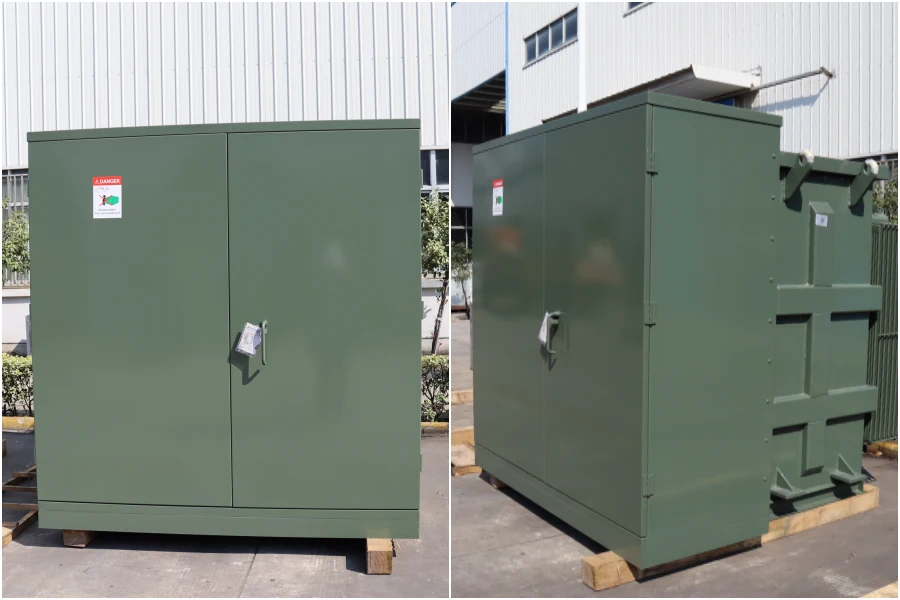
Pad-mounted transformers are self-contained, low-profile, tamper-proof power distribution centers designed for surface mounting on concrete foundations. They are the standard choice for modern commercial office parks, master-planned residential developments, and underground utility conversions.
-
Engineering Advantages: The integrated heavy-gauge steel enclosure features isolated medium-voltage and low-voltage compartments with secure, padlockable interlocking doors. This eliminates the need for protective perimeter fencing, making them safe for public spaces.
-
Feed Configurations: Available in Alimentación en bucle (configured with two separate high-voltage bushing mechanisms per phase, facilitating seamless integration into open or closed ring-main distribution topologies for enhanced grid redundancy) or Radial Feed (configured for single-source end-of-line configurations).
-
Safety Integration: Utilizes dead-front high-voltage terminations via insulated, screened elbow connectors, eliminating exposed live parts within the cable management zones.
-
Especificaciones técnicas: Engineered according to IEEE C57.12.34 y IEC 60076 benchmarks, incorporating bay-on-net overcurrent protection fuses coupled with current-limiting backup fuses to isolate faults without system-wide disruption.
3.2 Pole-Mounted Transformers: Cost-Efficient Overhead Infrastructure
Engineered for direct installation on single or H-frame utility poles within overhead medium-voltage distribution grids.
-
Engineering Advantages: Minimizes civil engineering installation footprints, optimizes air-cooling exposure, and offers an exceptionally low upfront capital-to-kVA ratio.
-
Design & Environmental Resilience: Housed in cylindrical, hermetically sealed, anti-corrosive hot-dip galvanized or epoxy-coated steel tanks designed to withstand severe weather, high salt spray in coastal zones, and avian nesting hazards.
-
Protection Framework: Typically coupled with external surge arresters (metal-oxide varistors) and dropout expulsion fuses mounted directly above the high-voltage porcelain or polymer bushings to safeguard against atmospheric lightning strikes and line-to-ground faults.
3.3 Oil-Immersed Transformers: High Efficiency and Longevity
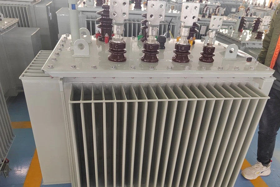
The most widely deployed distribution transformer globally, utilizing processed mineral oil or synthetic esters for both electrical insulation and thermal energy transport.
-
Engineering Advantages: Excellent dielectric strength, superior self-healing capabilities after minor localized electrical arcs, and an exceptionally high thermal mass that handles short-term overload conditions.
-
Core-and-Winding Topology: Incorporates high-permeability, grain-oriented silicon steel (CRGO) or amorphous metal alloys for the core laminations, paired with high-purity electrolytic copper or electrical-grade aluminum windings wound in continuous disk or layer configurations.
-
Structural Formats: Available in Hermetically Sealed formats (where the oil is entirely sealed from the atmosphere, utilizing corrugated tank walls that expand and contract to accommodate fluid thermal variations, eliminating oil oxidation and moisture ingress) or Conservator Tank systems (incorporating a separate expansion vessel fitted with a desiccant silica gel breather to filter out ambient atmospheric moisture).
3.4 Dry-Type Transformers: Safety-Critical Indoor Deployments
Dry-type transformers utilize solid dielectric insulation materials, eliminating flammable liquid coolants.
                  [VPI or Cast Resin Structure]
                         ┌───────────┐
                         │   HV/LV   │
          ⚡ Air Flow ──► │  Windings │ ──► Heat Dissipated Naturally
                         │ (No Oil)  │
                         └───────────┘
-
Engineering Advantages: Inherently fire-safe, self-extinguishing, and free from fluid-leakage hazards. This completely eliminates the need for expensive oil-containment dikes, blast walls, or complex fire-suppression systems.
-
Manufacturing Methodologies:
-
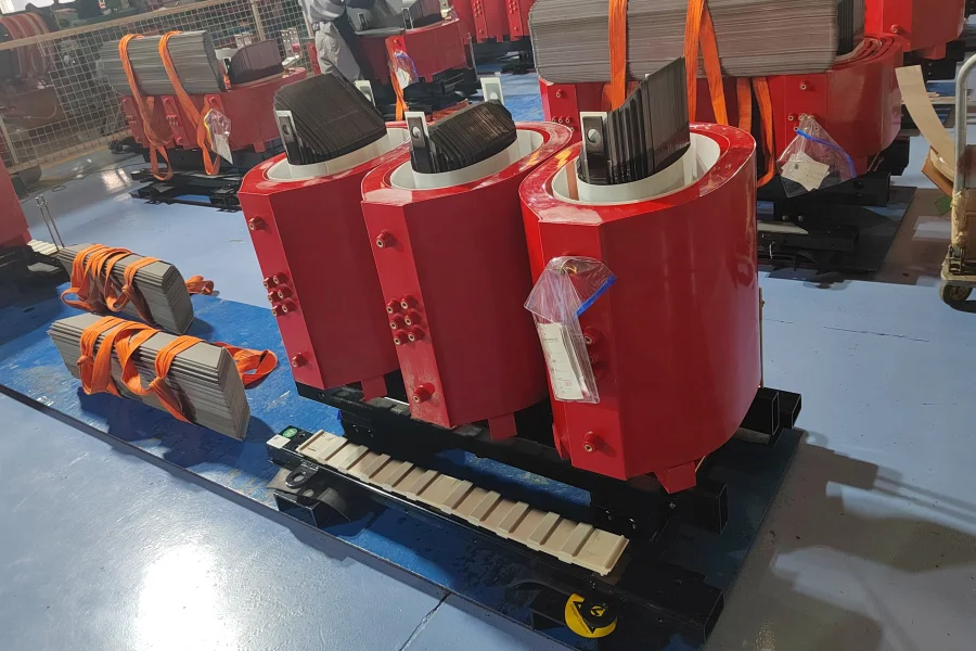
Cast Resin (CR): Windings are encapsulated within a vacuum-molded reinforced epoxy resin matrix. This provides high mechanical strength, resistance to short-circuit radial forces, and protection against moisture and airborne chemical contaminants. Ideal for highly humid marine environments and heavy industrial settings.
-
Vacuum Pressure Impregnation (VPI): Windings utilize high-temperature Class H or Class R insulation materials pre-impregnated with high-grade varnish under vacuum and pressure cycles. This ensures excellent electrical stress distribution and acoustic damping.
-
-
Primary Application Sectors: Commercial skyscrapers, healthcare facilities, deep-level subterranean mining networks, high-security data centers, and indoor multi-tier utility substations.
4. IEC vs. ANSI/IEEE Technical Frameworks
Navigating global procurement requires a clear understanding of the design differences between CEI (Comisión Electrotécnica Internacional) y ANSI/IEEE (American National Standards Institute / Institute of Electrical and Electronics Engineers) standards. These frameworks shape everything from testing protocols and structural designs to safety margins.
┌────────────────────────────────────────────────────────────────────────┐
│                        GLOBAL STANDARDS CROSSROADS                     │
├────────────────────────────────────┬───────────────────────────────────┤
│           IEC FRAMEWORK            │         ANSI/IEEE FRAMEWORK       │
├────────────────────────────────────┼───────────────────────────────────┤
│ • Focus: Modular, Functional       │ • Focus: Conservative, Robust     │
│ • Loss Evaluation: Strict Limits   │ • Loss Evaluation: Total Cost (TOC)│
│ • Standard: IEC 60076 Series       │ • Standard: C57 Series            │
└────────────────────────────────────┴───────────────────────────────────┘
4.1 Structural and Insulation Philosophy
-
IEC Standards (e.g., IEC 60076 series): Prevailing across Europe, Asia, Africa, and the Middle East. IEC standards emphasize physical optimization, modular flexibility, and a functional design approach. Temperature rise calculations are routinely benchmarked at 60K for top-oil and 65K for windings above ambient baselines.
-
ANSI/IEEE Standards (e.g., C57 series): Dominant throughout North America and parts of Latin America. ANSI designs favor highly conservative, robust physical profiles. Components are engineered with larger active material volume fractions, yielding higher Basic Insulation Levels (BIL) and larger mechanical safety margins to withstand harsh operational conditions.
4.2 Technical Comparison Matrix
| Parameters & Compliance Criteria | IEC 60076 Framework Specifications | ANSI / IEEE C57 Series Specifications |
| Standard Temperature Rise Limits | 65 K winding / 60 K top-oil | 65 K winding / 65 K top-oil (with premium options for 55/65 K overloading) |
| Short-Circuit Duration Threshold | Calculated explicitly based on system impedance (typically 2.0 seconds standard) | Fixed duration thresholds (2.0 seconds standard up to 4.0 seconds depending on kVA classification) |
| Bushing & Termination Formats | Typically open porcelain/polymeric or plug-in insulated outer-cone screen connectors | Standardized dead-front elbow connectors or exposed spade configurations with strict NEMA hole spacing |
| Loss Evaluation Framework | Fixed component tolerances with penalties for exceeding specified no-load/load maximums | Total Owned Cost (TOC) optimization algorithm (A and B factors for core/copper losses) |
| Basic Insulation Level (BIL) | Step-tiered structure matched to nominal grid voltages (e.g., 75 kV BIL for a 11 kV nominal system) | Generally higher standard thresholds (e.g., 95 kV or 150 kV BIL for comparative voltage systems) |
5. Correct kVA Selection Method: Engineering Practice
Selecting a transformer’s capacity based on current peak loads without accounting for transient dynamics can lead to premature system failure. Follow this rigorous four-step engineering methodology to determine the correct kVA size.
Step 1: Establish the True Continuous Coincident Load
Do not simply sum the nameplate kVA of all connected downstream loads. This leads to massive over-sizing. Apply a verified diversity/coincidence factor (eta_coincidence) based on the operational profile of the facility:
P_coincident = (Sum of P_static_loads) * eta_coincidence
Step 2: Compensate for Non-Linear Loads and Harmonic Profiles
If the facility contains variable speed drives (VFDs), LED lighting networks, server racks, or arc furnaces, the resulting harmonic currents will induce massive eddy-current losses in the transformer windings and core saturation. You must calculate the system’s K-factor profile:
K-Factor Calculation Logic:
K = Sum of (I_h^2 * h^2)
Where h represents the harmonic order, and I_h represents the fraction of total RMS current at that harmonic. For high K-factor environments, specify a factory-derated transformer or select an explicitly engineered K-factor rated transformer (K-4, K-13, K-20) featuring dual neutral conductors and electrostatic shielding.
Step 3: Account for High-Transient Inrush Profiles
Electric motors demand massive reactive inrush currents during direct-on-line (DOL) startup, often reaching 6 to 8 times their steady-state rated operating current. The transformer must have sufficient thermal and magnetic capacity to limit instantaneous voltage drop (Delta V) to less than 10% during start-up sequences to prevent downstream contactors from dropping out:
Delta V ≈ [ I_inrush * (R * cos_phi + X * sin_phi) ] / V_{text{nominal}}
Step 4: Factory-Incorporate Long-Term Expansion Buffers
Standard utility and industrial projections require a 20% to 30% infrastructure capacity reserve. A transformer operating continuously at 70% to 80% of its nominal nameplate rating runs at peak thermodynamic and electrical efficiency, leaving ample room for future expansion without overloading the dielectric insulation system.
6. Common Engineering Mistakes in Procurement
Over decades of diagnosing site failures and reviewing faulty client RFQs, the EverNew Engineering Team has identified five persistent engineering mistakes made during transformer procurement.
┌────────────────────────────────────────────────────────────────────────┐
│                        TOP 5 PROCUREMENT PITFALLS                      │
├────────────────────────────────────────────────────────────────────────┤
│ ❌ Under-sizing Capacity by Ignoring Motor Inrush Transients            │
│ ❌ Mixing IEC Component Topologies with ANSI Grid Enclosures           │
│ ❌ Neglecting Symmetrical Short-Circuit Sizing Standards               │
│ ❌ Incorrect Liquid-Dielectric / Environmental Placement Selection     │
│ ❌ Eliminating Future Operational Growth Expansion Margins             │
└────────────────────────────────────────────────────────────────────────┘
-
Under-sizing Capacity by Ignoring Motor Inrush Transients: Sizing a transformer purely for steady-state continuous loads often results in deep voltage dips and control system dropouts during large motor start-ups.
-
Mixing IEC Component Topologies with ANSI Grid Enclosures: Attempting to install European-style plug-in outer-cone terminations into a North American dead-front pad-mounted compartment creates component interference and violates electrical clearance boundaries.
-
Neglecting Symmetrical Short-Circuit Sizing Standards: Specifying a standard low-impedance transformer on a high-fault utility grid without verifying the winding mechanical bracing capability can lead to immediate mechanical collapse of the windings during the first external fault event.
-
Incorrect Liquid-Dielectric Selection for the Environment: Installing standard mineral oil-immersed transformers indoors or immediately adjacent to public waterways without secondary containment dikes creates severe environmental and fire safety liabilities.
-
Eliminating Future Operational Growth Expansion Margins: Eliminating the 20% to 30% capacity buffer to save on upfront capital costs often requires a full transformer replacement or redundant unit additions within just a few years of commissioning.
7. The Total Owned Cost (TOC) Evaluation Methodology
Smart engineering procurement prioritizes long-term efficiency over low initial bid prices. The Total Owned Cost (TOC) methodology quantifies the true financial impact of transformer losses over the asset’s operational life.
         ┌──────────────────────────────────────────────────────┐
         │              TOTAL OWNED COST (TOC)                  │
         └──────────────────────────┬───────────────────────────┘
                                    │
           ┌────────────────────────┴────────────────────────┐
           ▼                                                 ▼
   [Initial Capital Cost]                          [Lifetime Cost of Losses]
   (Purchase Price of Unit)                     - Core (No-Load) Losses (A * P0)
                                                - Winding (Load) Losses (B * Pk)
The evaluation formula for TOC calculation is structured as follows:
TOC = C_purchase + (A * P0) + (B * Pk)
Dónde:
-
C_purchase = The initial ex-factory procurement cost of the transformer.
-
P0 = The guaranteed No-Load Loss (Core Loss) in kilowatts (kW), generated continuously by magnetic hysteresis and eddy currents in the silicon steel core as long as the transformer is energized, regardless of load.
-
Pk = The guaranteed Load Loss (Winding/Copper Loss) in kilowatts (kW), generated by the I2R resistance of the conductor windings when under full load conditions.
-
A = The evaluated financial capitalization cost per kilowatt of No-Load Loss, determined by utility power costs, capitalization period, and operational hours ($/kW, typically ranging from $4,000 to $9,000/kW depending on regional energy costs).
-
B = The evaluated financial capitalization cost per kilowatt of Load Loss ($/kW, typically ranging from $1,500 to $4,500/kW, heavily weighted by the expected loading factor of the transformer).
By applying this methodology during bid evaluations, buyers frequently discover that an energy-efficient transformer with a higher upfront purchase price yields a significantly lower TOC, saving hundreds of thousands of dollars over its operating life. EverNew utilizes ultra-high-grade CRGO M100-23D o Amorphous Metal Alloy cores to achieve some of the lowest P0 values in the industry, maximizing long-term financial returns for our clients.
8. Why Engineering Support Matters: The EverNew Advantage
A distribution transformer is a system-engineered asset. It cannot be sourced out of a standard commodity catalog. At Transformador EverNew, we combine decades of manufacturing experience with rigorous engineering analysis to provide premium power solutions.
       [Raw Project Data Input] ──► (Voltages, Load Profiles, Environment)
                  │
                  ▼
       [EverNew Engineering Design] ──► (Finite Element Analysis, Core Optimization)
                  │
                  ▼
   ┌──────────────┼──────────────┐
   ▼              ▼              ▼
[IEC/ANSI]   [Thermal/SC]   [Custom Form]
Compliance    Simulation     Factors
Advanced In-House Capabilities
-
Fully Compliant Design Architecture: Our designs are verified to comply fully with both IEC 60076 y ANSI/IEEE C57 international standards, ensuring seamless integration into any regional grid.
-
Project-Specific Form Factor Customization: We engineer custom terminal arrangements, distinct enclosure dimensions, specialized paint systems for highly corrosive environments, and low-profile designs tailored for tight physical spaces.
-
Advanced Simulation Analysis: Our team utilizes state-of-the-art Finite Element Method (FEM) software to model localized magnetic flux distributions, verify mechanical short-circuit withstand capabilities, and map thermal hot spots under peak overload conditions before manufacturing begins.
-
Proven Global Logistics Experience: We have successfully delivered heavy power assets to utilities, major industrial zones, and remote infrastructure projects across Asia, the Middle East, Africa, Europe, and South America.
-
Comprehensive Turnkey EPC Engineering Support: We provide dedicated technical documentation support, comprehensive structural drawing packages, schematic control diagram layouts, and factory testing documentation to support your engineering teams through every project phase.
🛠️ EverNew Internal Link Portfolio:
Deep dive into our industrial manufacturing, testing protocols, and project history:
9. Request Technical Support or a Quotation
If you are managing an active utility upgrade, an industrial expansion, or a large-scale EPC infrastructure project, the engineering team at EverNew is ready to assist. Contact us today to receive:
-
Comprehensive transformer capacity sizing validation and harmonic derating calculations.
-
Detailed technical data sheets, structural dimension drawings, and clear vector configuration options.
-
Highly competitive, transparent factory-direct pricing optimized for your long-term Total Owned Cost (TOC).
-
Tailored mechanical and electrical design modifications to solve your specific site constraints.
👉 Contact the EverNew Transformer Engineering Team today to schedule an engineer-to-engineer technical consultation and secure a rapid, professional quote for your project.
Was this guide helpful?
Are you currently specifying a distribution transformer for a unique application or navigating challenging regional grid standards? Let us know what technical challenges you are facing. What specific integration or performance issues can our engineering team help you solve next?
