
In today’s interconnected world, power transformers play a crucial role in ensuring reliable energy distribution. Whether you are in North America, South America, Europe, Asia, Africa, or Oceania, understanding a power transformer diagram is essential for making informed purchasing decisions, ensuring proper installation, and optimizing long-term maintenance and costs.
As a global manufacturer, Evernew Transformer specializes in high-quality pad mounted transformers, pole mounted transformers, dry type transformers, and substation transformers, serving industrial, commercial, and utility customers across key markets such as the USA, Canada, UK, Germany, France, Netherlands, Italy, Australia, Portugal, Russia, South Africa, and beyond.
1. What is a Power Transformer Diagram?
A power transformer diagram is a schematic illustration showing the internal and external components of a transformer, including windings, bushings, tap changers, and electrical connections. It provides a visual reference that helps engineers, technicians, and procurement managers understand:
-
Transformer structure and design layout
-
Electrical connection points between high-voltage (HV) and low-voltage (LV) circuits
-
Safety and grounding mechanisms
-
Locations of accessories such as radiators, gauges, and control boxes
This makes it a critical tool for selecting the right transformer, ensuring accurate installation, and troubleshooting operational issues.
2. Why Buyers Need to Understand Transformer Diagrams
For procurement specialists, EPC contractors, and utility companies, a power transformer diagram offers significant benefits:
-
Accurate Product Comparison: Evaluate competing products based on winding configuration, cooling systems, and dimensions.
-
Simplified Installation: Clear wiring and component layouts prevent costly mistakes during setup.
-
Maintenance Planning: Visual access to parts like oil valves and temperature indicators helps with routine checks.
-
Compliance Verification: Ensure the transformer meets IEC, IEEE, and local standards before purchasing.
-
Cost Forecasting: Anticipate expenses related to installation, accessories, and long-term operation.
Learn More:How Long Does It Take to Replace a Power Transformer?
3. Common Types of Power Transformer Diagrams
Different transformer applications require different diagram types. Below are the most commonly used:
3.1 Distribution Transformer Diagram
Used for low-to-medium voltage distribution networks, such as urban neighborhoods or industrial parks.
Key Information Included:
-
Rated power (e.g., 400 kVA, 11kV/0.4kV)
-
Core and coil weight, oil weight, total weight
-
HV and LV schematic wiring
-
Manufacturer details and compliance certifications
Applications: Street lighting, residential areas, small industrial facilities.
Oil-immersed Distribution Transformer Diagram
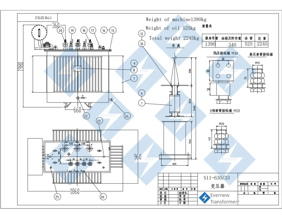
The 630kVA oil distribution transformer diagram from Evernew Transformer delivers a precise technical overview for engineers, utility companies, and global buyers. Built for reliable medium-voltage power distribution, this transformer is widely used in industrial facilities, commercial buildings, and substations across North America, South America, Europe, Asia, and Africa.
Key Highlights
-
Capacity & Ratings:
-
Rated Power: 630kVA
-
Designed for high efficiency and stable performance in diverse environments.
-
-
Voltage Specifications:
-
HV terminals for medium-voltage input
-
LV terminals for safe, efficient output
-
-
Dimensions:
-
H: 1980mm | W: 1860mm | D: 960mm
-
Compact for urban networks and utility installations
-
-
Weight Breakdown:
-
Machine: 1390 kg
-
Oil: 525 kg
-
Total: 2245 kg (accurate for shipping and installation planning)
-
-
Component Layout:
-
HV & LV bushings, tap changer, pressure relief device
-
Grounding terminals, lifting lugs, and clear labeling for safe maintenance
-
3.2 Dry Type Transformer Diagram
Designed for safe indoor and outdoor applications, dry type transformers are ideal for environments where oil-filled units are not suitable. Typically available in capacities ranging from 50–9000 kVA, they are widely used in commercial and industrial settings.
Highlights:
-
Safe, oil-free design with high fire resistance and low environmental impact.
-
Clear layout of HV and LV windings, terminals, and cooling channels for easy inspection and maintenance.
-
Excellent heat dissipation through natural or forced air cooling (AN/AF).
-
Voltage conversion for medium to low-voltage applications, such as 10kV to 400V.
-
High efficiency and reliability, reducing energy losses and maintenance costs.
1600 KVA Dry Type Transformer Diagram
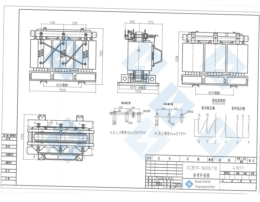
Evernew Transformer presents a 1600 kVA dry type transformer diagram, offering a clear, technical overview for engineers, contractors, and global buyers. This schematic is designed for medium-voltage distribution systems, providing reliable power for commercial, industrial, and urban applications across North America, Europe, Asia, South America, Africa, and other regions.
The diagram includes all critical specifications and component details, helping with transformer selection, installation planning, maintenance, and safety compliance.
Key Information Displayed in the Diagram
A. Transformer Dimensions
-
Height: 1338 mm
-
Width: 1520 mm
-
Depth: 1170 mm
Compact, space-saving design for indoor substations, data centers, hospitals, and high-rise buildings.
B. Transformer Technical Data
-
Rating (Capacity): 1600 kVA
-
Primary Voltage (HV): 10 kV
-
Secondary Voltage (LV): 400 V
-
Frequency: 50/60 Hz
-
Winding Material: Copper or aluminum (customizable)
-
Polarity: Clearly marked for correct installation
-
Efficiency: High energy efficiency with minimal losses
-
No-Load Losses: Optimized for low energy wastage during idle operation
-
On-Load Losses: Reduced through advanced design
-
Impedance: Balanced to ensure system stability
-
Cooling Method: AN/AF (Air Natural / Air Forced)
-
Insulation Class: High-temperature resistant resin, fire-retardant and eco-friendly.
C. Component Layout & Positioning
The diagram shows the exact positions of all critical parts:
-
HV and LV terminal layouts for safe and easy wiring.
-
Cooling ducts for natural or forced air circulation.
-
Core and coil assembly clearly marked for maintenance reference.
-
Support frame and lifting lugs for transportation and installation.
-
Bushing connections clearly identified as A, B, C, and neutral points.
-
Clear vector group diagram for understanding electrical configuration.
D. Weight Information
-
Core and Windings Weight: Clearly listed for logistics planning.
-
Frame and Accessories Weight: Detailed for safe handling and installation.
-
Total Weight: Simplifies transportation calculations.
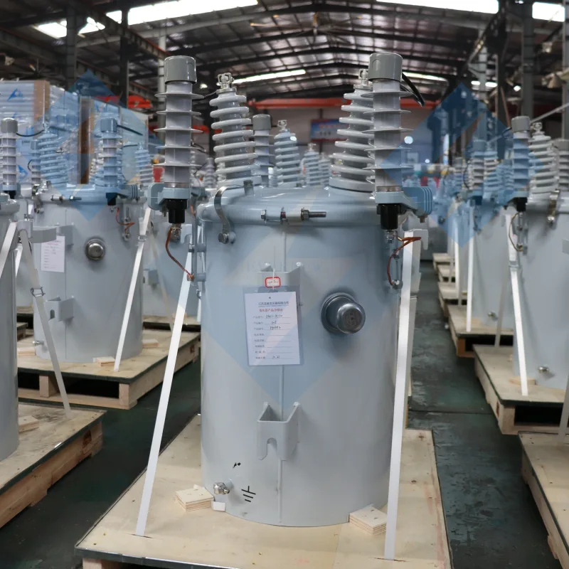
3.3 Single-Phase /Pole Mounted Transformer Diagram
Designed for light commercial loads or standalone applications.
Typical Features:
-
Single-phase winding layout
-
Tap changer positions for voltage adjustment
-
Detailed weight and loss data (no-load and on-load losses)
Applications: Agricultural equipment, small-scale industrial machinery.
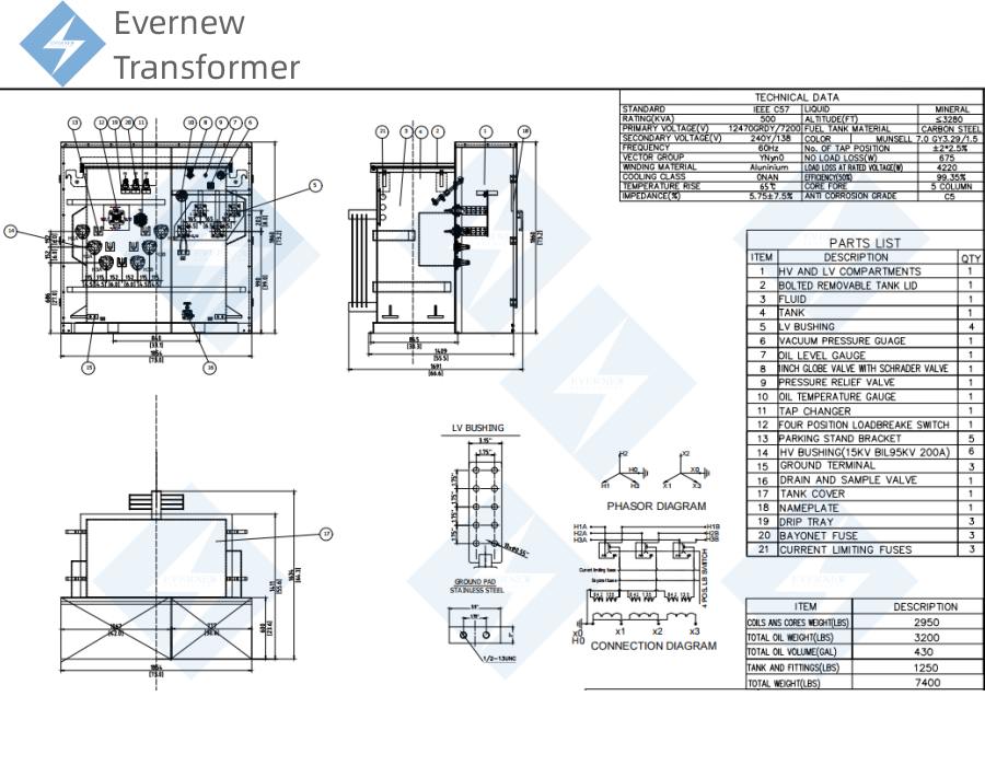
Evernew 50 KVA Pole Mounted Transformer Diagram
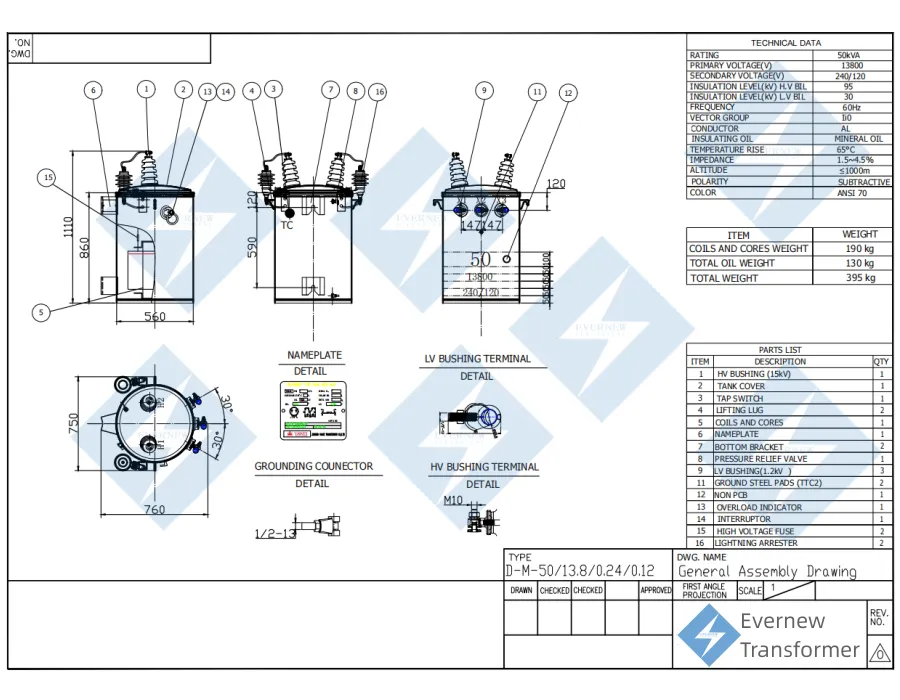
The Evernew Transformer 50 kVA pole mounted distribution transformer is built to deliver efficient and reliable power distribution for rural and urban networks. This transformer is widely applied in North America, South America, Europe, Asia, Africa, and other regions, providing dependable service for utilities, contractors, and industrial projects.
This diagram offers a complete reference with technical specifications, dimensions, weight data, and component positions, ensuring smooth planning, safe installation, and proper maintenance.
A. Technical Specifications
-
Rated Capacity: 50 kVA
-
Primary Voltage (HV): 13.8 kV
-
Secondary Voltage (LV): 240/120 V
-
Insulation Level:
-
HV BIL: 95 kV
-
LV BIL: 30 kV
-
-
Frequency: 60 Hz
-
Vector Group: Single Phase
-
Conductor: Copper or Aluminum
-
Insulating Oil: Mineral Oil
-
Temperature Rise: 55 °C
-
Maximum Altitude: 5100 m
-
Standard Color: ANSI 70 (light gray for outdoor use)
B. Dimensions
-
Overall Height: 860 mm
-
Body Width: 560 mm
-
Top Diameter: 760 mm
Its compact size is ideal for pole-mounted systems, especially in rural grids and suburban areas.
C. Weight Information
-
Coils & Cores: 190 kg
-
Oil Weight: 130 kg
-
Total Weight: 395 kg
These details help with shipping, handling, and installation planning.
D. Component Identification
The diagram clearly shows all key elements for operation and safety:
-
HV Bushing Terminals (M10): Primary high-voltage connection points.
-
LV Bushing Terminals: Safe and stable low-voltage outputs.
-
Tap Switch: For voltage adjustment to maintain stable supply.
-
Pressure Relief Valve: Prevents excessive internal pressure.
-
Overload Indicator & Interrupter: Monitoring and protection features.
-
Lightning Arrester: Protection against surges and lightning strikes.
-
Grounding Connector: Ensures secure grounding for safety.
-
Lifting Lugs: Easy and safe equipment handling during installation.
E. Parts List
- 1、HV Bushing (15 kV)
- 2、Tank Cover
- 3、Tap Switch
- 4、Lifting Lugs
- 5、Coils and Cores
- 6、Nameplate
- 7、Bottom Bracket
- 8、Pressure Relief Valve
- 9、LV Bushing (1.2 kV)
- 10、Ground Steel Pads (CTC2)
- 11、Drain Plug
- 12、Overload Indicator
- 13、Interrupter
- 14、High Voltage Fuse
- 15、Lightning Arrester
3.4 Three-Phase Power Transformer Diagram
Essential for large-scale power networks and high-demand facilities.
Diagram Contents:
-
Delta (Δ) or Wye (Y) connections for HV and LV sides
-
Winding temperature indicators and explosion-proof safety mechanisms
-
Radiator configurations for cooling optimization
Applications: Substations, renewable energy plants, data centers.
Evernew 110KV 40 MVA Power Transformer Diagram

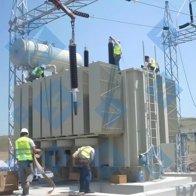
In Central Asia, where winters are extremely harsh, a new industrial park urgently needed a stable and efficient power source. The local utility worked with Evernew Transformer to design a custom 220kV power transformer built to handle severe cold and heavy loads.
Evernew’s technical team traveled to the site, guiding the installation process step by step — from lifting and wiring to final testing.
Once energized, the transformer delivered reliable power despite the freezing conditions. The client praised Evernew:
“This project has greatly strengthened our regional power grid.”
The successful installation not only improved local energy stability but also expanded Evernew Transformer’s footprint in the Central Asian market.
3.5 Pad Mounted Transformer Diagram
A sealed, ground-level transformer popular in North America and Europe for underground power distribution.
Advantages:
-
Tamper-proof design for public safety
-
Compact footprint ideal for urban environments
-
Simplified wiring connections shown clearly in the diagram
Markets: USA, Canada, UK, Germany.
UL Certified Pad Mounted Transformer Diagram from China Manufacturer Evernew
4. How to Read a Power Transformer Diagram
Understanding a power transformer diagram involves breaking it down step-by-step:
Step 1: Analyze the Title Block
Includes transformer classification, rating, and manufacturer details such as Evernew Transformer’s factory location and contact information.
Step 2: Identify Symbols
Common symbols:
-
Rectangle with parallel lines: Transformer core
-
Dots or numbers: Winding terminals
-
Triangle or Y: Delta or Wye connections
Step 3: Locate Key Components
Look for:
-
HV and LV bushings
-
Tap changers
-
Radiators and cooling systems
-
Protective devices like pressure relief valves
Step 4: Trace Electrical Connections
Follow wiring paths to understand how energy flows between the transformer’s input and output circuits.
5. Power Transformer Diagram and Global Standards
Compliance is vital for international trade. Evernew Transformer ensures all products meet or exceed the following:
-
IEC 60076 – International Electrotechnical Commission
-
IEEE C57 – Institute of Electrical and Electronics Engineers
-
UL/cUL Certification – For North American markets
-
ISO 9001 & ISO 14001 – Quality and environmental management
This guarantees seamless integration into utility grids across the USA, Europe, Asia, and beyond.
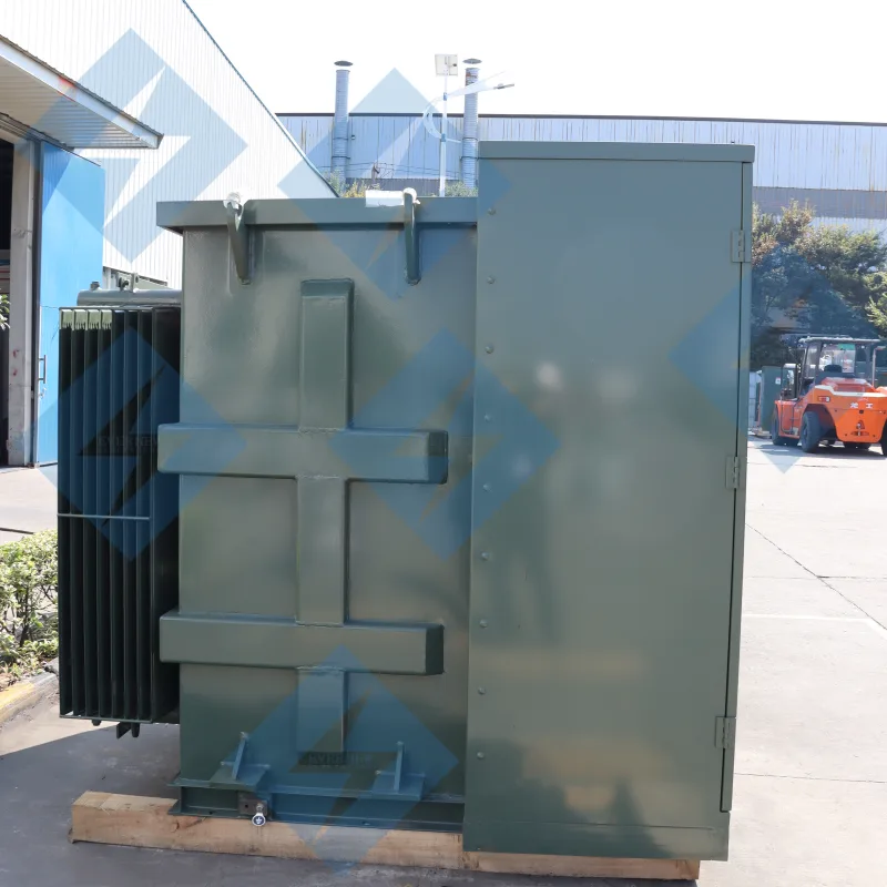
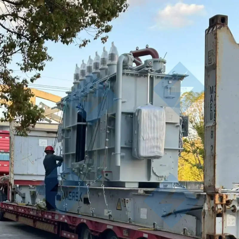
This custom 110kV power transformer from Evernew Transformer has successfully completed all rigorous testing procedures and is now loaded and ready for shipment, ensuring reliable performance for our client.
Get In Touch6. Cost Insights for Buyers
Transformer costs vary widely depending on size, design, and features. Here’s a rough guide:
- Residential Transformer: The typical cost ranges from $1,000 to $5,000.
- Pad Mounted Transformer: Prices usually fall between $7,000 and $25,000.
- Pole Mounted Transformer: These are generally priced from $3,000 to $15,000.
- 3-Phase Substation Transformer: Costs are much higher, typically ranging from $50,000 to over $500,000.
- Installation and commissioning fees
- Logistics and international shipping
- Optional accessories like smart monitoring systems
- Local import duties and compliance testing
7. Installation Considerations
Proper installation directly impacts transformer lifespan and efficiency.
For Pad Mounted Transformers:
-
Ensure a stable, level foundation
-
Maintain adequate clearance for ventilation
-
Follow local underground cable routing standards
For Pole Mounted Transformers:
-
Secure mounting brackets to prevent vibration
-
Properly insulate HV lines to minimize arcing
-
Grounding systems must comply with safety codes
For Substation Transformers:
-
Use fire-resistant barriers for oil-filled units
-
Integrate with SCADA systems for remote monitoring
-
Perform pre-energization testing to verify wiring integrity
8. Troubleshooting with Power Transformer Diagrams
When performance issues arise, diagrams become invaluable for diagnostics.
Common Issues:
-
Overheating: Check radiator and cooling systems.
-
Oil Leaks: Inspect gaskets and sample oil for contamination.
-
Unbalanced Voltage: Verify winding connections and tap positions.
-
Noise or Vibration: Examine core grounding and loose components.
Diagnostic Tools:
-
Infrared thermography for hotspot detection
-
Dissolved gas analysis (DGA) for oil-filled units
-
Multimeter testing for continuity and voltage verification
9. Why Evernew Transformer is Your Global Partner
With decades of expertise, Evernew Transformer is committed to delivering premium power transformers backed by:
-
Factory-direct wholesale pricing
-
Custom engineering for diverse global markets
-
Strong after-sales support and technical training
-
Reliable logistics to key hubs in USA, Europe, Asia, and Africa
Whether you’re sourcing for utility grids, renewable energy projects, or industrial complexes, Evernew Transformer provides trusted solutions that combine performance, safety, and cost-efficiency.
10. Final Thoughts
A power transformer diagram is more than a technical illustration — it’s a roadmap for selecting, installing, and maintaining the backbone of modern power distribution systems. By understanding these diagrams, buyers and engineers can make smarter decisions, reduce operational risks, and ensure long-term energy reliability.
With Evernew Transformer as your partner, you gain access to world-class engineering expertise, comprehensive product ranges, and a global network that delivers excellence to every project, no matter where you are located.