Introduction: Why Transformer Testing Matters?
Transformers are crucial components of electrical transmission and distribution systems, playing a vital role in voltage regulation and power efficiency. Regular testing is essential to ensure reliability, efficiency, and safety, as transformers can degrade over time due to operational stresses, environmental conditions, or manufacturing defects.
As one of China’s top transformer manufacturers, Evernew Transformer has over 30 years of experience in producing high-quality transformers. Our products are exported to over 70 countries, including the United States, Canada, Russia, Europe, South America, Africa, and Asia, and meet CE, UL, and GOST certifications. We conduct rigorous transformer testing to comply with international standards and ensure superior performance.
This guide provides a detailed breakdown of transformer testing methods, helping professionals and engineers evaluate transformer performance effectively.
Understanding Transformer Testing Parameters
1. Key Transformer Parameters
Before conducting any transformer test, it is important to understand the key parameters that define transformer efficiency, performance, and reliability.
a. Core Loss (Iron Loss) Testing
Definition: Core loss (or iron loss) occurs due to hysteresis and eddy currents in the transformer’s magnetic core. These losses occur even when the transformer is not supplying load current.
Testing Method:
Open-circuit test: The primary winding is energized with rated voltage while the secondary remains open.
Power measurement: Measures the energy lost as heat in the core.
Analysis: High core loss may indicate poor core material, improper lamination, or excessive magnetic flux.
b. Copper Loss (Winding Loss) Testing
Definition: Copper loss occurs due to the resistance of the transformer windings when current flows. This loss increases with higher current loads.
Testing Method:
Short-circuit test: The secondary winding is shorted, and a reduced voltage is applied to the primary.
Current measurement: Determines losses based on P = I²R, where R is the resistance of the winding.
Analysis: Excessive copper loss may indicate poor conductor material, loose connections, or overheating issues.
c. Winding Resistance Measurement
Definition: Measures the resistance of transformer windings to assess electrical integrity.
Testing Method:
DC Resistance Test using a micro-ohmmeter.
Four-terminal measurement to eliminate lead resistance errors.
Analysis: Higher-than-expected resistance may suggest winding deterioration, corroded contacts, or inter-turn faults.

2. Essential Electrical Parameters
a. Primary Current Measurement
Definition: The current flowing through the primary winding when the transformer is energized.
Importance:
Higher-than-expected primary current could indicate overloading or winding short circuits.
Lower-than-expected current may result from poor impedance matching or incorrect circuit configuration.
Testing Method:Apply nominal voltage to the primary winding and measure current.
Compare with rated values provided in transformer specifications.
b. Secondary Voltage Measurement
Definition: The voltage output at the secondary winding under load conditions.
Importance:
High secondary voltage could indicate voltage regulation issues, insulation breakdown, or resonance effects.
Low secondary voltage may suggest overloading, excessive winding resistance, or incorrect tap settings.
Testing Method:Use a voltmeter to measure secondary voltage under no-load and full-load conditions.
Ensure voltage ratios match transformer design specifications.
c. Leakage Inductance Measurement
Definition: Leakage inductance refers to the portion of magnetic flux that does not link both primary and secondary windings.
Importance:
High leakage inductance may lead to poor voltage regulation in high-frequency applications.
Low leakage inductance is preferable for power transformers but might not be suitable for applications like ignition circuits.
Testing Method:Use an LCR meter or an impedance analyzer to measure leakage inductance.
d. Winding Capacitance Measurement
Definition: Measures the capacitance between transformer windings or between windings and the core.
Importance:
Higher capacitance can cause transformers to saturate at lower voltages, affecting frequency response.
Lower capacitance is preferable for high-frequency transformers to reduce parasitic losses.
Testing Method:Measure inter-winding capacitance using an LCR bridge or capacitance meter.

Common Transformer Testing Methods
1. Open-Circuit (No-Load) Test
Objective: To measure iron losses and no-load current.
Procedure:
Connect rated voltage to the primary winding with the secondary open.
Measure input power, current, and voltage.
Calculate core loss using power measurement.
2. Short-Circuit Test
Objective: To measure copper losses and determine equivalent circuit parameters.
Procedure:
Short the secondary winding and apply a reduced voltage to the primary.
Measure current, voltage, and power loss.
Compute copper loss (P = I²R).
3. Insulation Resistance Test
Objective: To check the integrity of insulation between windings and core.
Procedure:
Use a megohmmeter (megger) to apply high DC voltage.
Measure insulation resistance in MΩ (megohms).
Low insulation resistance indicates moisture ingress, insulation degradation, or contamination.
4. Partial Discharge (PD) Test
Objective: To detect small electrical discharges that indicate early-stage insulation failure.
Procedure:
Apply high AC voltage and monitor partial discharge signals.
Excessive discharge may indicate voids, cracks, or contamination within insulation.
5. Dielectric Withstand (Hi-Pot) Test
Objective: To ensure the insulation can withstand high voltages without breakdown.
Procedure:
Apply overvoltage (1.5 to 2 times rated voltage) for a short period.
Check for any insulation breakdown or leakage currents.
6. Transformer Oil Testing (for Oil-Immersed Transformers)
Objective: To assess insulation oil quality and detect contaminants.
Tests Performed:
Dissolved Gas Analysis (DGA) for detecting overheating and arcing.
Dielectric Strength Test to measure oil’s insulating capability.
Moisture Content Analysis to prevent insulation degradation.
Evernew Transformer: Excellence in Transformer Manufacturing & Testing
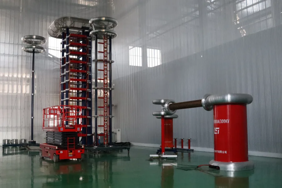
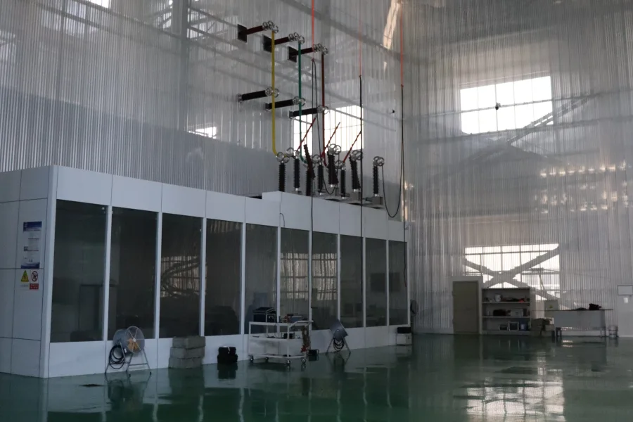
At Evernew Transformer, we implement rigorous testing procedures to ensure every transformer meets the highest performance and safety standards. Our state-of-the-art testing facilities include:
✅ Automated High-Voltage Testing Lab – Performs impulse and dielectric withstand tests.
✅ Partial Discharge Testing – Detects early-stage insulation faults.
✅ Thermal Rise & Efficiency Testing – Ensures optimal performance.
✅ Transformer Oil Analysis Lab – Enhances oil-immersed transformer reliability.
✅ Online Monitoring & Predictive Maintenance – Extends transformer lifespan.
Conclusion: Ensuring Reliable Transformer Performance
Comprehensive testing is crucial for transformer reliability, efficiency, and longevity. By implementing open-circuit, short-circuit, insulation, and advanced diagnostic tests, engineers can detect potential issues early and prevent failures.
Evernew Transformer is committed to delivering high-quality, rigorously tested transformers to customers worldwide. For customized transformer solutions and expert consultation, contact us today!

