Dry Type Transformer Types: The Ultimate Industrial Engineering Guide to Cast Resin, VPI, VPE, Isolation, and K-Factor Transformers
1. Introduction to Modern Dry Type Transformer Engineering
In the modern global landscape of medium-voltage power distribution, industrial automation, and commercial electrical infrastructure, selecting the appropriate magnetic core components is a critical technical decision. Historically, liquid-immersed transformers utilizing highly refined hydrocarbon mineral oil dominated both transmission grids and local distribution networks. This historical preference stemmed from the exceptional dielectric breakdown strength and superior thermal convection properties inherent to liquid dielectrics.
However, accelerating urbanization, the proliferation of indoor substations, stringent fire protection codes (such as NFPA 70 and the National Electrical Code), and severe environmental mandates regarding soil and groundwater contamination have driven a massive, industry-wide transition toward transformadores de tipo seco.
A dry-type distribution transformer completely eliminates the need for liquid dielectrics. Instead, the primary and secondary electrical windings, the laminated core topology, and the internal busbar connections are insulated via solid-state dielectric materials, ambient air flow, and specialized technical polymer resins. This fundamental shift in material science significantly alters the thermodynamic profiles, mechanical shear resistance, and electrical impedance performance of the transformer under both continuous baseline operations and transient short-circuit fault conditions.
The Strategic Shift: Liquid-Immersed vs. Dry-Type Transformers
The engineering transition from legacy liquid-filled units to advanced solid-insulated dry type systems is governed by clear, quantifiable operational trade-offs:
- Fire Hazard Mitigation and Safety Compliance: Liquid-immersed units present a catastrophic risk of fire or physical explosion if an internal high-energy arc flashes through the mineral oil, heating it past its fire point (typically 140°C to 160°C). Advanced dry type transformers utilize inherently self-extinguishing materials that severely mitigate flame propagation, fully satisfying the strict requirements of Euroclass F1 fire behavior ratings. This allows them to be safely installed inside commercial high-rises, hospitals, and residential basements without blast-resistant concrete vault construction.
- Environmental Protection and Civil Engineering Cost Reductions: Liquid-filled systems require complex civil infrastructure, including dedicated concrete oil containment bunds, fire-suppression deluge piping, and firewall barriers. Dry type installations eliminate the risk of oil leaks, ground spills, and chemical contamination. This direct elimination erases costly civil construction requirements and minimizes the physical footprint required in the electrical room.
- Optimized Maintenance Profiles and Lower OPEX: Liquid systems demand strict, recurring maintenance schedules involving regular oil sampling, Dissolved Gas Analysis (DGA), dielectric moisture titration, and routine gasket replacements. Conversely, dry type distribution units operate virtually maintenance-free. They require only periodic physical vacuuming of surface dust and regular infrared thermography scans of structural terminal connections, resulting in a substantially lower long-term Operational Expenditure (OPEX).
2. Fundamentals of Dry Type Insulation Material Science and Thermodynamics
To accurately evaluate the operational thresholds, overloading capabilities, and degradation timelines of various dry type systems, it is essential to analyze the interaction between dielectric insulation materials, Arrhenius thermal degradation mechanics, and environmental classifications.
Insulation Classes and Thermal Margins
The operational life expectancy of a dry-type power transformer is directly governed by the thermal degradation rate of its internal solid insulation system. The thermal insulation classes are strictly codified by international standard bodies like IEC 60085 and IEEE C57.12.01. These technical standards define the maximum allowable continuous operating temperature at the absolute hottest localized point within the winding structure, commonly known as the winding hot-spot.
- Class B Insulation System: Engineered for a maximum allowable temperature of 130°C. This includes an allowable average winding temperature rise of 80°C above a standard 40°C baseline ambient temperature, leaving a dedicated hot-spot margin allowance of 10°C.
- Class F Insulation System: Rated for a maximum allowable temperature of 155°C. This configuration permits a continuous average winding temperature rise of 100°C, with a calculated hot-spot margin allowance of 15°C. Class F is widely considered the baseline standard for standard industrial applications.
- Class H Insulation System: Engineered for a maximum allowable temperature of 180°C. This high-performance class permits a 125°C average winding temperature rise and a 15°C hot-spot allowance. It is widely specified for heavy industrial plants, traction systems, and data center environments.
- Class R / Class C Insulation System: Rated for extreme maximum temperatures up to 220°C. This high-density system allows for a massive 150°C average winding temperature rise and a 30°C hot-spot allowance, heavily utilized in high-output traction applications and marine vessels where physical space is extremely constrained.
The mathematical equation for verifying thermal compliance under continuous full load is defined as follows: The Winding Hot-Spot Temperature is equal to the Ambient Temperature, plus the Average Winding Temperature Rise, plus the designated Hot-Spot Margin Allowance. Exceeding this calculated temperature limit triggers rapid, irreversible chemical aging of the polymer chains.
Thermodynamics, Heat Dissipation, and the Arrhenius Principle
Unlike oil-filled units where internal heat is transferred via continuous liquid convection currents to external tank radiator fins, dry type units rely entirely on a combination of solid-state thermal conduction through the epoxy or varnish insulation layers, and convective air currents moving vertically across the exposed coil duct surfaces.
The heat generated inside the transformer is a combination of copper or aluminum winding resistive losses (calculated as Current squared multiplied by Resistance, or I2R losses) and core magnetic hysteresis and eddy current losses. If these combined losses exceed the natural convective heat dissipation rate, the internal winding temperature escalates. This triggers accelerated thermal aging governed by the Arrhenius reaction rate theory. This chemical theory dictates that the rate of insulation polymer degradation roughly doubles for every 7°C to 10°C increase above its rated maximum thermal insulation class limit.
Environmental, Climatic, and Fire Behavior Classifications (IEC 60076-11)
To ensure global standardization and safe industrial procurement, the IEC 60076-11 standard defines specific operational performance criteria that manufacturers must independently test and certify:
- Environmental Class E0: No condensation occurs on the transformer structure, and ambient particulate pollution is completely negligible. This is strictly suitable for clean, climate-controlled indoor electrical rooms.
- Environmental Class E1: Occasional condensation and limited ambient pollution can occur, typical of standard ventilated indoor industrial substations.
- Environmental Class E2: Frequent condensation or heavy atmospheric pollution is present. This is specified for heavy industrial foundries, paper mills, and offshore wind platforms.
- Environmental Class E3: Severe condensation and extreme pollution levels are present, such as coastal installations exposed to continuous salt spray or heavy mining operations with highly conductive dust.
- Climatic Class C1: The transformer is suitable for continuous operation down to ambient temperatures of -5°C, but can withstand storage and transport down to -25°C.
- Climatic Class C2: The transformer is fully rated for operation, rapid energization, transport, and storage at severe arctic ambient temperatures down to -25°C.
- Climatic Class C3: Specialized low-temperature operation rated for continuous service down to -50°C, mandatory for extreme high-latitude industrial deployments.
- Fire Behavior Class F1: Transformers subjected to high external fire hazards. The design mandates that the emission of toxic halogen gases and opaque smoke must be minimized, and the unit must inherently self-extinguish within a specified timeframe once the external ignition source is removed.
3. Magnetic Core Metallurgy and Energy Efficiency Standards
The operational efficiency and long-term financial performance of a dry-type distribution transformer are heavily influenced by the metallurgy of its magnetic core structure.
Grain-Oriented Silicon Steel (GOES) Cores
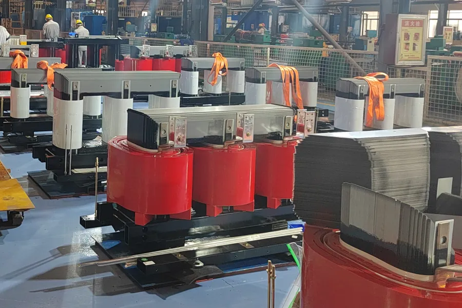
The standard core material utilizes high-grade Grain-Oriented Silicon Steel (GOES) laminations. These iron-silicon alloys are processed through cold-rolling techniques that precisely align the crystal grain orientation along the rolling direction. This precise alignment drastically reduces magnetic reluctance and minimizes core hysteresis losses. Individual laminations are coated with an inorganic insulating film to interrupt horizontal electrical paths, minimizing eddy current losses within the core structure.
Amorphous Metal Core Transformers (AMDT)
For high-efficiency grids and ultra-green corporate applications, Amorphous Metal Core Transformers (AMDT) represent a major technological leap. Instead of a crystalline atomic structure, amorphous cores utilize an alloy of iron, boron, and silicon that is rapidly cooled from a liquid state to form a non-crystalline, glass-like atomic matrix. The absence of a crystalline structure allows for effortless magnetic domain rotation under alternating currents. This structural advantage reduces no-load core losses by up to 70% to 80% compared to standard GOES cores. This enables operators to drastically cut down continuous utility energy waste.
Regulatory Efficiency Mandates (DOE and EU Ecodesign)
Governments worldwide enforce strict statutory maximum allowance thresholds for transformer energy losses, requiring highly optimized core and winding configurations:
- United States Department of Energy (DOE) Mandates: Enforces strict minimum efficiency percentages across distribution transformers under 10 CFR Part 431. These regulations require manufacturers to utilize high-grade GOES or amorphous cores to hit specific efficiency targets under a 35% reference load factor.
- European Union Ecodesign Directive: Enforces strict Tier 2 eco-efficiency limits on maximum allowable load and no-load losses for all dry type units connected to European distribution grids, effectively banning low-efficiency manufacturing architectures.
4. Deep-Dive: Cast Resin Dry Type Transformers (CRDT)
Cast Resin Dry Type Transformers (CRDT) are globally recognized as the pinnacle of high-dielectric, mechanically stable solid insulation engineering. They dominate the market in high-density urban infrastructure, critical data centers, and advanced transportation networks.
Manufacturing Chemistry and Vacuum Enclosure Systems
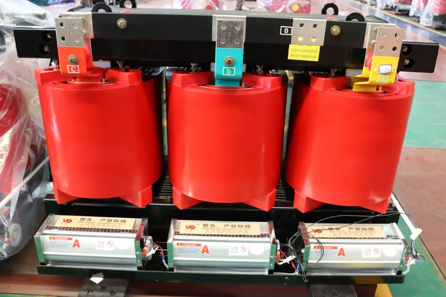
The fabrication of cast resin units centers around the complete encapsulation of the High Voltage (HV) and Low Voltage (LV) electrical windings inside an impenetrable, solid matrix of epoxy resin blended with silica powder or trihydrate alumina fillers. This filler material is highly engineered: it aligns the thermal expansion coefficient of the cured epoxy resin with that of the internal copper or aluminum conductors, preventing micro-cracking during rapid load heating and cooling cycles.
The rigorous manufacturing workflow utilizes highly controlled Vacuum Casting Systems. First, the coils are precisely wound using foil or rectangular conductors. Inter-turn insulation consists of thin film technical polymers. The finished coil is then positioned inside a highly accurate, polished steel mold geometry. The entire mold assembly is introduced into a heavy industrial vacuum chamber.
The atmospheric pressure inside the chamber is pulled down close to an absolute vacuum (typically less than 1 mbar). This critical step forcefully evacuates all residual moisture and microscopic air pockets trapped deep within the winding layers. While still under vacuum, a pre-heated, low-viscosity liquid epoxy resin mixture is injected into the mold. The vacuum ensures the resin penetrates every interstitial space down to the micrometer scale. Finally, the filled mold is transferred to a computer-controlled curing oven, where a carefully mapped multi-stage thermal profile cross-links the polymer chains, transforming the liquid into a highly stable, solid thermoplast block.
Partial Discharge Characterization and Long-Term Reliability
For engineers, the defining quality metric for any cast resin transformer is its Partial Discharge (PD) performance. Partial discharge represents localized, microscopic electrical breakdowns in an insulation system under high voltage stress. In cast resin, these discharges only occur within microscopic air voids trapped inside the solid resin matrix during a flawed manufacturing process. Over continuous years of operation, PD slowly erodes the polymer matrix from the inside out, eventually leading to a catastrophic complete dielectric puncture.
According to strict IEC 60076-11 testing standards, premium cast resin units must exhibit exceptionally low PD levels, typically less than or equal to 10 pC (picocoulombs) when electrically stressed at 1.3 times their rated nominal phase-to-ground voltage. Achieving this metric requires immaculate manufacturing control during the vacuum degassing stage.
Structural Performance Under Short-Circuit Shock Forces
During an external through-fault short-circuit on the grid, transformer windings experience immediate, immense mechanical electro-dynamic forces. Radial forces attempt to push the outer winding outward while simultaneously crushing the inner winding inward toward the steel magnetic core. Axial forces compress the vertical height of the coils, threatening to shear the physical mounting blocks.
The solid cast resin block provides extraordinary mechanical rigidity. The high Young’s modulus of the cured glass-fiber-reinforced epoxy matrix locks the conductors absolutely firmly in place. This monolithic structure completely eliminates inter-turn micro-movements and prevents physical deformation, even under fault currents that can spike to 20 or 30 times the unit’s nominal current rating for several electrical cycles.
5. Deep-Dive: Vacuum Pressure Impregnated (VPI) Transformers
While cast resin represents the premium tier for severe environments, Vacuum Pressure Impregnated (VPI) transformers offer an entirely different, highly efficient design philosophy optimized for specific indoor applications and favorable weight constraints.
Technical Architecture and Open-Wound Insulation
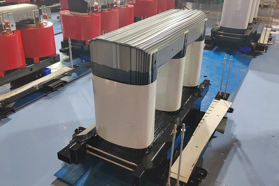
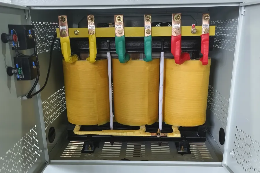
Instead of completely encapsulating the windings in a thick, heavy resin block, VPI technology relies on applying multiple layers of open-weave, high-temperature insulation materials (such as DuPont Nomex paper, aramid fibers, or woven technical fiberglass) directly around the conductors. This dry assembly is then treated with a high-grade, solventless polyester or silicone varnish under alternating cycles of deep vacuum and high pressure.
The VPI Manufacturing Cycle
The manufacturing process begins with the dry assembly of the coils. The completed core-and-coil assembly is pre-baked in a large industrial oven to drive off all ambient humidity absorbed by the aramid papers. The hot assembly is then placed into a heavy-walled steel pressure vessel.
A deep vacuum is pulled to evacuate all remaining air from the porous insulation layers. Following this, the vessel is flooded with the liquid varnish. The chamber is then pressurized, typically using dry nitrogen gas to a pressure of 6 to 8 bar. This immense positive pressure forcefully drives the liquid varnish deep into the microscopic pores of the aramid fibers and between the conductor joints. After impregnation, the assembly is drained and baked at temperatures exceeding 150°C. This final curing stage polymerizes the liquid varnish into a resilient, cohesive, and moisture-resistant protective barrier coating.
Advanced Thermal Performance and Mass Efficiency
VPI units are frequently engineered using Class H (180°C) or Class R (220°C) high-temperature insulation systems. Because the protective varnish layers are vastly thinner than a cast resin shell, the thermal resistance between the hot inner conductors and the ambient cooling air is significantly reduced. This allows for extremely rapid heat dissipation directly across the vertical cooling ducts.
Furthermore, VPI units exhibit a remarkably lower mass profile compared to cast resin variants of the same MVA rating. The absence of heavy solid resin molds minimizes the total weight of the active part. This makes VPI units highly advantageous for structural installations where structural floor loading capacities are strictly limited, such as the upper mechanical levels of commercial high-rises or mobile industrial skids.
Environmental Limitations and Open Ventilated Vulnerabilities
The open-weave nature of VPI construction means that while the conductors are thoroughly coated, they are not hermetically sealed like a cast resin block. The surface retains microscopic texturing. Consequently, VPI units are highly sensitive to sustained high humidity environments and direct liquid ingress. In heavy industrial environments with airborne conductive dust (such as iron filings in foundries or carbon black), particulates can slowly settle into the exposed winding grooves, creating electrical tracking paths that can lead to phase-to-phase flashovers.
6. Deep-Dive: Vacuum Pressure Encapsulated (VPE) Transformers
Vacuum Pressure Encapsulated (VPE) transformers are engineered to bridge the operational and environmental gap between standard VPI systems and premium Cast Resin systems.
Comparative Materials Analysis: VPE vs. VPI
While the manufacturing procedure utilizes a vacuum and pressure chamber cycle nearly identical to standard VPI, the vital difference lies in the chemistry of the impregnating agent. VPE processes utilize a highly viscous, high-solid-content silicone or specialized epoxy formulation, rather than a thin, fluid varnish.
Through successive immersion, vacuum, and pressure cycles, the VPE process deliberately builds a thick, rubberized, or semi-rigid protective envelope around the entire outer surface of the exposed windings. This conformal layer is millimeter-scale in thickness, providing a vastly superior barrier against moisture ingress and harsh chemical attack, without requiring the heavy steel casting molds and the massive weight penalties associated with a full cast resin design.
Target Applications in Harsh Environments
VPE units excel in industrial applications that expose electrical infrastructure to harsh, corrosive environmental conditions but cannot structurally or economically support the weight and thermal footprint of cast resin units. Typical high-performance deployment environments include coastal and offshore marine infrastructure (where the air is heavily laden with corrosive sodium chloride) and chemical processing facilities containing airborne vapors like hydrogen sulfide or ammonia that would rapidly degrade standard VPI polyester varnishes.
7. Dry Type Isolation Transformers and K-Factor Systems
A dry type isolation transformer is a highly specialized engineering component designed not merely to step voltage up or down, but to completely decouple two circuits galvanically. This decoupling prevents the transmission of stray ground currents, common-mode electrical noise, and high-frequency transient voltage spikes.
Galvanic Isolation Physics and Electrostatic Faraday Shielding
The core physical principle of an isolation transformer relies on separating the primary input winding and the secondary output winding via a physical distance filled with solid dielectrics. Crucially, high-quality isolation transformers integrate a grounded Electrostatic Faraday Shield. This is typically a thin, continuous sheet of non-magnetic copper or aluminum foil meticulously wrapped between the primary and secondary winding layers.
The presence of this Faraday shield fundamentally alters the internal capacitive coupling of the transformer. In a standard distribution transformer, high-frequency common-mode electrical noise on the grid passes directly from the primary to the secondary through inter-winding capacitance. The Faraday shield intercepts this capacitance, breaking it into two distinct series capacitors that are connected directly to the earth ground. Consequently, dangerous high-frequency transient currents are shunted safely and directly to the ground grid, preventing electrical noise from corrupting sensitive downstream electronic loads.
Harmonic Distortion and K-Factor Engineering
In modern electrical systems, non-linear loads such as variable speed drives (VFDs), switching power supplies, LED lighting matrices, and data center servers inject severe high-frequency harmonic currents (3rd, 5th, 7th, 11th, and 13th harmonics) back into the electrical distribution system. These harmonic currents do not contribute to real power output but dramatically increase the transformer’s operating temperature via two distinct phenomena: elevated skin effect losses in the winding conductors and intensified eddy current losses within the magnetic core laminations.
To safely mitigate this extra thermal loading, engineers specify K-Factor rated transformers. The K-Factor rating is an empirical weighting factor that quantifies a transformer’s ability to handle harmonic currents without exceeding its rated insulation class temperature rise:
- K-1 Rating: Designed for standard linear loads, such as incandescent lighting and basic resistive heating elements, with zero harmonic content.
- K-4 Rating: Engineered for mild non-linear loads, such as standard commercial office buildings utilizing basic telecommunications equipment and fluorescent lighting ballasts.
- K-13 Rating: Specially engineered for dense data center server architectures, extensive medical imaging departments, and centralized school computer laboratories.
- K-20 and Higher Ratings: Heavy-duty industrial configurations designed for massive VFD installations, solid-state rectifiers, and heavy SCR-controlled induction welding lines.
A high K-factor transformer incorporates specific design adjustments. Winding conductors are constructed using multiple parallel strands of transposed insulated wire to minimize high-frequency skin effect losses. Neutral busbars are upsized to twice the size of the phase conductors to safely carry the additive triplen harmonics (3rd, 9th, 15th) that accumulate in the neutral leg of three-phase systems. Furthermore, the magnetic core is physically upsized and operated at a reduced flux density to prevent magnetic saturation under harmonic distortion.
8. Quantitative Engineering Comparison Matrix
To assist procurement engineers, system designers, and plant operators in making accurate technical selections, the following data table provides a direct, comprehensive engineering comparison of the primary dry type transformer configurations:
| Technical Parameter | Cast Resin (CR) | Vacuum Impregnated (VPI) | Vacuum Encapsulated (VPE) | Faraday Shielded Isolation |
|---|---|---|---|---|
| Standard Capacity Range | 100 kVA to 30 MVA | 50 kVA to 15 MVA | 50 kVA to 15 MVA | 1 kVA to 5 MVA |
| Maximum System Voltage | Up to 52 kV Class | Up to 36 kV Class | Up to 36 kV Class | Up to 15 kV Class |
| Rigidez dieléctrica | Very High (> 20 kV/mm) | Moderate (> 10 kV/mm) | High (> 15 kV/mm) | High (Design Dependent) |
| Partial Discharge Level | Exceptional (≤ 10 pC) | High (Inherent to design) | Moderate (≤ 50 pC) | Minimal (Low Noise) |
| Short-Circuit Resistance | Outstanding (Rigid Matrix) | Very Good | Very Good | Good |
| Moisture/Salt Resistance | Impervious (E2 / E3 Rated) | Susceptible (Requires E0/E1) | Highly Resistant | Enclosure Dependent |
| Common-Mode Noise Rejection | Standard Baseline | Standard Baseline | Standard Baseline | Exceptional (> 60 dB shunted) |
| Relative Cost Baseline Index | 1.4 to 1.6 (Premium) | 1.0 (Baseline Economy) | 1.2 to 1.3 (Mid-Range) | 1.1 to 1.3 (Application Specific) |
9. Thermal Management, Forced Air Ventilation, and Cooling Control Logic
Dry type power transformers rely on standard cooling methodology designations defined by international norms. Modifying the physical cooling method directly alters the safe continuous power output capacity of the electrical unit.
AN (Air Natural) Cooling Mode
In a standard AN configuration, the transformer dissipates its thermal energy purely via natural atmospheric air buoyancy. Ambient air enters through the bottom ventilation louvers of the steel enclosure, absorbs heat as it contacts the internal vertical cooling ducts of the energized coils, and naturally rises out through the top exhaust ports due to thermal buoyancy. This passive mode represents the baseline continuous rating of the unit (defined as 100% nameplate capacity).
AF (Air Forced) Cooling Mode
AF cooling introduces specialized, low-noise mechanical cross-flow fan bars positioned horizontally beneath the low voltage and high voltage winding blocks. When activated, these fans force high-velocity ambient air directly upward through the internal winding channels. This forced turbulent airflow drastically increases the convective heat transfer coefficient, enabling the transformer to safely strip away the extra heat generated by substantial current overloads. Activating AF cooling allows the unit to sustain a continuous or semi-continuous capacity surge of 30% to 40% above its baseline AN rating.
ANAF (Air Natural / Air Forced) Dual-Mode Automation
Modern industrial installations universally utilize ANAF configurations managed by digital temperature controllers. These controllers are hard-wired to embedded PT100 Resistance Temperature Detectors (RTD) physically inserted into the hot-spots of the low-voltage windings. The logic operates dynamically:
- AN Baseline Stage: The transformer runs silently under normal loads. The cooling fans remain unpowered, eliminating auxiliary energy draw.
- AF Fan Activation Stage: If the load demand spikes and the winding temperature reaches a primary threshold (e.g., 130°C for a Class F insulation system), the digital controller closes its auxiliary contacts, energizing the cooling fans to rapidly stabilize internal temperatures.
- Alarm Warning Stage: If thermal escalation continues due to a sustained grid overload and the winding temperature reaches a secondary safety limit (e.g., 145°C), the controller triggers a local and remote SCADA alarm to warn operators.
- Catastrophic Trip Stage: If temperatures hit the absolute maximum safety limit of the insulation system (e.g., 155°C), a final relay contact instantly trips the main upstream high-voltage circuit breaker. This cuts off power and saves the transformer from complete internal breakdown.
10. Comprehensive Procurement Criteria and Site Selection Matrix
Selecting the proper dry type transformer architecture is a high-stakes decision that requires a multi-faceted assessment of environmental factors, electrical limits, and long-term financial parameters.
- Environmental Ingress Protection (IP) and NEMA Enclosures: For clean indoor sub-stations, a highly ventilated IP20 or IP21 (NEMA 1) enclosure is sufficient and cost-effective. For outdoor industrial applications, a ruggedized, weather-proof enclosure rated at IP23, IP44, or IP54 (NEMA 3R) is mandatory, usually paired with internal structural anti-condensation space heaters to prevent morning dew accumulation during shutdown periods.
- Altitude Derating Calculations: Standard dry type transformers are thermally engineered for operation at altitudes less than or equal to 1000 meters above sea level. At higher elevations, the lower atmospheric density significantly reduces both the air’s dielectric breakdown voltage and its volumetric thermal cooling capacity. For installations above this baseline, the transformer’s capacity must be mathematically derated by approximately 0.5% for every 100 meters above the 1000-meter mark.
- Seismic Zone Structural Reinforcement: For installations located in seismically active regions, the standard core-clamping structures and enclosure tie-down brackets must be mechanically reinforced. Procurement specifications must explicitly mandate compliance with local seismic acceleration codes (such as Uniform Building Code Zone 4 or Eurocode 8 standards).
- Acoustic Noise Control: Dry type units generate an acoustic hum caused by core magnetostriction. In noise-sensitive applications like hospitals, commercial offices, or luxury residential complexes, strict maximum sound power level limits (dBA) must be mandated per NEMA ST-20 benchmarks. This often requires the inclusion of vibration-dampening elastomeric pads beneath the core base frame.
- Economic Life-Cycle Costing (LCC): Procurement teams must avoid the trap of evaluating units solely on initial capital expenditure (CAPEX). A deeply discounted transformer with high internal core iron and winding copper losses will incur massive financial penalties over a 30-year operational lifespan due to wasted electricity. The standard Life-Cycle Cost is calculated as: LCC = CAPEX + (Factor A × No-Load Core Losses) + (Factor B × Load Copper Losses). Factor A and Factor B represent the capitalized financial cost per watt based on local utility tariffs, load profiles, and internal rates of return (IRR). Evaluating units based on this formula guarantees the lowest Total Cost of Ownership.
11. Application-Specific Industrial Selection Guidelines
To optimize field performance, different industries demand distinct dry-type architectures tailored to their specific operational hazards:
Data Centers and Critical Cloud Infrastructure
Data centers operate around the clock with highly non-linear, harmonic-rich server loads. The primary design goal is absolute uptime and maximum safety. The optimal choice is a Transformador de resina moldeada with a K-13 or K-20 rating, paired with an electrostatically shielded primary loop. The cast resin matrix guarantees maximum protection against accidental fires, while the K-rating easily neutralizes harmonic heating.
Marine Vessels and Offshore Oil Rigs
Marine environments subject electrical components to continuous mechanical vibration, high ambient humidity, and highly corrosive salt air. Physical space inside engine rooms is extremely limited. The optimal choice is a Vacuum Pressure Encapsulated (VPE) or space-optimized Class R/C Cast Resin unit. The VPE silicone skin or cast resin envelope isolates the conductors from saline moisture, while the robust structural frame resists continuous maritime vibration.
Renewable Energy Integration (Solar and Wind Farms)
Renewable step-up transformers are exposed to severe cyclic loading profiles, expanding during peak daylight or high winds and dropping to zero at night. This rapid thermal cycling induces severe mechanical stresses. The optimal choice is a Vacuum Casting Cast Resin Transformer. The high mechanical strength of the epoxy matrix accommodates cyclic thermal expansion without developing structural micro-fractures, ensuring grid stability.
12. Complete Testing Protocols, Quality Assurance, and Factory Acceptance Testing (FAT)
Before any dry type transformer is cleared to leave the manufacturing facility, it must undergo strict quality assurance testing to confirm its electrical and physical integrity. Tests are classified into Routine Tests (performed on 100% of production units) and Type/Special Tests (performed on design prototypes).
Routine Factory Testing (Per IEC 60076-11 and IEEE C57.12.91)
- Measurement of Winding Resistance: Performed using high-precision digital micro-ohmmeters across all phases and terminal taps. This establishes an exact baseline for calculating copper I2R losses and verifies that internal joints are free of defects.
- Verification of Voltage Ratio and Vector Group Phase Displacement: Confirms that the physical turn ratio matches design calculations and ensures the unit can operate in parallel with other transformers without phase mismatch.
- Measurement of Short-Circuit Impedance and Load Loss: The low-voltage terminal is short-circuited, and a reduced voltage is applied to the high-voltage winding until full rated current is achieved. This measures load losses and determines the exact transformer impedance percentage.
- Measurement of No-Load Loss and Excitation Current: The transformer is energized at full rated nominal voltage while the secondary remains open-circuit. This measures core excitation losses and core magnetizing current.
- Separate-Source AC Withstand Voltage Test (Applied Voltage): Verifies the dielectric strength of the insulation barriers between windings and from the windings to the grounded steel chassis by applying a high-amplitude industrial frequency voltage for 60 seconds.
- Induced Overvoltage Test: The transformer is excited at a higher voltage amplitude and frequency (typically 2 times nominal voltage at 100 Hz to 400 Hz) to confirm the dielectric integrity of the inter-turn and inter-layer insulation inside the coils without saturating the magnetic core.
Type and Special Engineering Tests
- Winding Temperature Rise Test: The transformer is subjected to full simulated thermal load losses within a sealed testing bay until thermal equilibrium is reached. Winding resistance differentials are measured to confirm full compliance with rated insulation class limits.
- Partial Discharge Measurement: A critical test for cast resin units to verify the absence of micro-voids within the encapsulated resin block, ensuring long-term dielectric stability.
- Anechoic Sound Level Measurement: Maps the acoustic output profile of the unit under full core excitation, confirming adherence to municipal or corporate noise limits per NEMA ST-20 or IEC benchmarks.
13. Maintenance, Diagnostics, and Lifecycle Troubleshooting
While dry type transformers are low-maintenance compared to liquid-filled units, establishing a proactive preventive maintenance framework is essential for achieving a 30- to 40-year operational life.
Routine Inspection Protocols
On a semi-annual basis, the transformer enclosure must be de-energized, isolated, and safely grounded. Maintenance teams should execute the following steps:
- De-dusting and Ventilation Clearing: Accumulations of atmospheric dust on the winding surface and within vertical cooling air ducts must be completely removed using industrial vacuums or dry, compressed nitrogen gas (regulated below 2 bar to prevent structural insulation erosion).
- Torque Verification: Due to continuous thermal expansion cycles, mechanical bolt connections on busbars and terminal taps can experience structural loosening. All electrical connections must be verified using calibrated torque wrenches to prevent high-resistance localized hot-spots.
Advanced Diagnostic Testing
- Insulation Resistance Testing (Megger Test): Performed using a digital insulation tester applying 2.5 kV or 5 kV DC between the windings and to the ground frame. Operators calculate the Polarization Index (PI), which is the ratio of the 10-minute insulation resistance to the 1-minute value. A PI value less than 1.5 indicates dangerous moisture absorption or severe particulate contamination, requiring immediate dry-out procedures before re-energization.
- Infrared Thermography: Conducted while the transformer is operating under full system load. Thermographic cameras instantly spot internal high-resistance connections or uneven thermal profiles across the cooling ducts, allowing operators to schedule maintenance before an unexpected outage occurs.
Frequently Asked Questions
Which dry type transformer type is most commonly used?
Transformadores de resina de moldeo en seco are the most widely specified dry type units globally due to their reliable moisture resistance, low partial discharge values, high mechanical strength under short-circuit conditions, and fire safety characteristics.
What is the core engineering difference between Cast Resin and VPI transformers?
The primary difference lies in the material science and manufacturing processes of their insulation systems. Cast Resin transformers completely encapsulate the active coils within a solid, thick block of epoxy resin using a vacuum casting mold. VPI (Vacuum Pressure Impregnation) transformers wrap the coils in porous high-temperature sheets (such as aramid paper) and dip them in an open varnish coating under cyclic pressure states, leaving the coils partially open and ventilated.
Can dry type transformers be installed in outdoor settings?
Yes. While the active elements of a dry type transformer cannot be directly exposed to rain, snow, or UV degradation, they can be deployed outdoors when installed within a weatherized, structurally rated enclosure (such as NEMA 3R, IP23, or IP54) equipped with anti-condensation space heaters and customized ventilation louvers.
How does an isolation transformer mitigate common-mode noise?
An isolation transformer separates its primary and secondary windings through galvanic isolation and introduces a grounded, non-magnetic copper Faraday shield between the coils. This shield shunts high-frequency common-mode noise and voltage transients directly to the earth ground grid, preventing electrical disturbances from passing through the inter-winding capacitance to downstream electronic equipment.
What standard protocols govern the testing of dry type transformers?
The primary international standards are IEC 60076-11 (defining environmental, climatic, and fire behavior classifications along with routine/type test codes) and IEEE C57.12.01 / IEEE C57.12.91 (which outline general requirements and test standards within North American jurisdictions).
Conclusión
Selecting the optimal dry type transformer architecture—whether navigating the premium structural reliability of Cast Resin, the lightweight mass efficiency of VPI, or the noise-shunting capabilities of a Faraday-shielded Isolation unit—is a critical step toward building a safe, resilient, and energy-efficient power distribution infrastructure. By evaluating installation environments, electrical parameters, and total life-cycle costs, engineers and buyers can ensure their systems operate reliably over a long service life.
Energy Transformer is a globally recognized engineering partner providing custom-manufactured dry type transformer solutions for international utility grids, heavy industrial plants, renewable energy integrations, and commercial high-rise infrastructure. Our dedicated technical engineering team is prepared to design and deliver custom Cast Resin and VPI solutions that perfectly align with your specific technical specifications and demanding local regulatory requirements. Contact our global engineering department today to comprehensively discuss your next power distribution project.
